30
2-5-3 High-density I/O Units Classified as Special I/O Units
Some High-density I/O Units are classified as Special I/O Units. Up to 10 Special
I/O Units can be connected to a PC. The Units have two 24-pin connectors. In
general, these Units control 32 I/O points, although some Units can control 128
I/O points when set for dynamic operation.
Refer to Appendix B Specifications for detailed specifications and dimensions of
the Units.
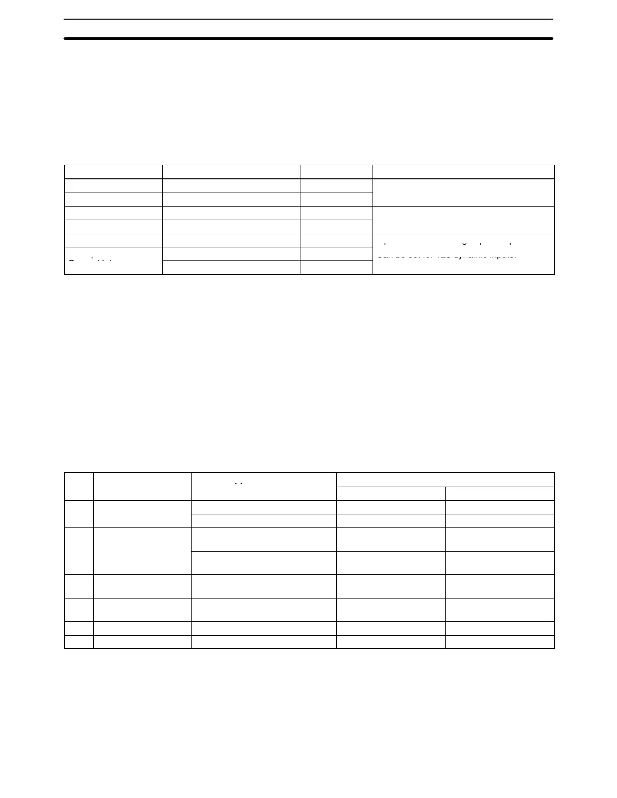
Unit Specifications Model Number Remarks
TTL Input Unit 5 VDC, 32 inputs C200H-ID501 8 pts can be set as high-speed inputs.
DC Input Unit 24 VDC; 32 inputs C200H-ID215
TTL Output Unit 5 VDC, 32 outputs C200H-OD501 Can be set for 128 dynamic outputs.
Transistor Output Unit 24 VDC; 32 outputs C200H-OD215
TTL I/O Unit 5 VDC, 16 inputs, 16 outputs C200H-MD501
8 pts can be set as high-speed inputs.
DC Input/Transistor
12 VDC; 16 inputs, 16 outputs C200H-MD115
Can be set for 128 dynamic inputs.
Output Unit
24 VDC; 16 inputs, 16 outputs C200H-MD215
Can be set for 128 dynamic inputs.
Note Refer to Optional Products, Appendix A Standard Models for a list of external
connectors.
Setting the Unit Number High-density I/O Units are each allocated 10 I/O words in the IR Area (IR 100 to
IR 199) by setting the unit number switch on the front of each Unit. The 10 words
begin with n, where n = IR 100 + 10 × unit number. For example, a Special I/O
Unit with a unit number of 3 would be allocated IR 130 to IR 139.
Always turn the PC power off before changing a Unit’s unit number. The new unit
number (0 to 9) will not be recognized unless the PC has been turned off.
Setting the DIP Switch The operation of High-density I/O Units is controlled by setting the pins of the
DIP switch on the back panel. The following table shows the function of each pin
and applicable Units.
Pin Function Applicable Units
Setting
ON OFF
1 Operating mode C200H-OD501/OD215 128 dynamic outputs 32 outputs
C200H-MD501/MD115/MD215 128 dynamic inputs 16 inputs, 16 outputs
2 High-speed input
1
C200H-ID501/ID215 Inputs 08 to 15 of CN2
are high-speed inputs.
Normal inputs
C200H-MD501/MD115/MD215 Inputs 08 to 15 of CN2
are high-speed inputs.
Normal inputs
3 High-speed input
minimum pulse width
2
C200H-ID501/ID215
C200H-MD501/MD115/MD215
4 ms 1 ms
4 Input response time
3
C200H-ID501/ID215
C200H-MD501/MD115/MD215
15 ms max. 2.5 ms max.
5 Data output mode
4
C200H-OD501/OD215 Positive logic Negative logic
6 Not used. --- --- ---
Note 1. Used in the C200H-MD501/MD115/MD215 only when pin 1 is OFF, setting
the Unit to static mode.
2. Used in the C200H-ID501/215, C200H-MD501/MD215/MD115/MD215
only when pin 2 is ON, setting the Unit to High-speed input mode.
3. Sets the input response time for normal inputs. When pin 2 is ON, CN2 08 to
15 are pulse-catch inputs. Other inputs can be used as normal inputs.
I/O Units Section 2-5