Appendix BSpecifications
161
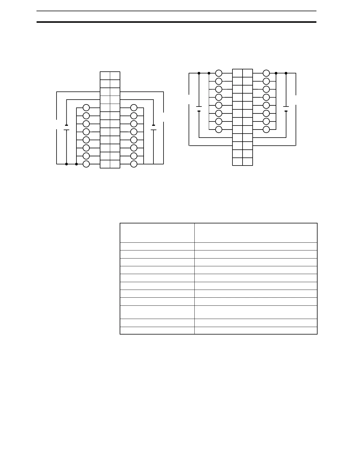
Terminal Connections
I/O word “n”
CN1
I/O word “n+1”
CN2
L L
L
+5 to 24 VDC +5 to 24 VDC
B
1
2
3
4
5
6
7
8
9
0
1
2
3
4
5
6
7
COM0
+
10
NC
11
NC
8
9
10
11
12
13
14
15
COM1
+
AB
0
1
1
2
2
3
3
4
4
5
5
6
6
7
7
8
COM2
9
8
9
10
11
12
13
14
15
COM3
10
NC
11
NC
NC
12
A
1
2
3
4
5
6
7
8
9
10
11
12
NC
NC
12
NC
1
2
3
4
5
6
7
8
9
10
11
12
5 to 24
VDC
5 to 24
VDC
5 to 24
VDC
5 to 24
VDC
L
L
L
L
L
L
L
L
L
L
L
L
L
L
L
+ +
+5 to 24 VDC+5 to 24 VDC
LL
L L
L L
L L
L L
L L
L L
Note 1. I/O word “n” is determined by the unit number setting (n = IR 100 + 10 × unit number).
2. The Unit will have 32 static output points when pin 1 of it’s DIP switch is OFF.
Transistor Output Unit C200H-OD215
(Used as 128-point Dynamic Output Unit)
Max. Switching Capacity 16 mA 4.5 VDC to 100 mA 26.4 VDC (see page
172)
800 mA/common, 3.2 A/Unit
Min. Switching Capacity None
Leakage Current 0.1 mA max.
Residual Voltage 0.7 V max.
ON Response Time 0.2 ms max.
OFF Response Time 0.6 ms max.
No. of Circuits 2 (dynamic, 64 points/circuit)
Internal Current Consumption 220 mA 5 VDC max.
Fuses 4 (1 fuse/common; fuses are not user-replacable.)
Power for External Supply
90 mA 5 to 24 VDC10% min.
(2.8 mA × number of ON outputs)
Weight 300 g max.
Dimensions 130×34.5×100.5 (H×W×D, in millimeters)