Appendix BSpecifications
163
4. The strobe signal has negative logic regardless of the setting of pin 5.
5. When the output device (such as a numeric display) does not have a pull-up resistor, it is necessary to
add a pull-up resistor between the + terminal of the power supply and each data (0 to 15) and strobe (0 to
15) terminal.
TTL I/O Unit C200H-MD501
(Used as I/O Unit with 16 Inputs and 16 Outputs)
Max. Switching Capacity 5 VDC 35 mA (280 mA/common, 560 mA/Unit;
output resistance 4.7 kW)
Min. Switching Capacity None
Leakage Current 0.1 mA max.
Residual Voltage 0.4 V max.
ON Response Time 0.2 ms max.
OFF Response Time 0.3 ms max.
No. of Circuits 2 (8 points/common)
Fuses 2 (1 fuse/common; fuses are not user-replacable.)
Power for External Supply 20 mA 5 VDC min. (1.2 mA × no. of outputs ON)
Rated Input Voltage 5 VDC
Operating Input Voltage 4.5 to 5.5 VDC
Input Impedance
1.1 kW
Input Current 3.5 mA (at 5 VDC)
ON Voltage 3.0 VDC min.
OFF Voltage 1.0 VDC max.
ON Response Time 2.5 ms/15 ms max. (switchable)
OFF Response Time 2.5 ms/15 ms max. (switchable)
No. of Circuits 2 (8 points/common)
High-speed Inputs 8 points (connector 2 terminals 8 to 15, when set)
Pulse width: 1 ms/4 ms min. (switchable)
Internal Current Consumption 180 mA 5 VDC max.
Weight 300 g max.
Dimensions 130×34.5×100.5 (H×W×D, in millimeters)
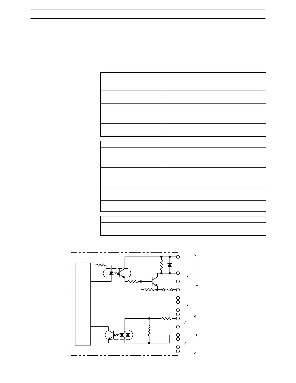
Circuit Configuration
CN1 (Output)
CN2 (Input)
OUT00
OUT07
COM0
OUT08
OUT15
COM1
Internal
Circuit
5 VDC
5 VDC
Fuse
4.7 kW
COM2
IN08
IN15
COM3
IN00
IN07
1.1 kW
2.4 kW
Output Specifications
(Connector 1)
Input Specifications
(Connector 2)
General Specifications