Appendix BSpecifications
183
DIP Switch Settings
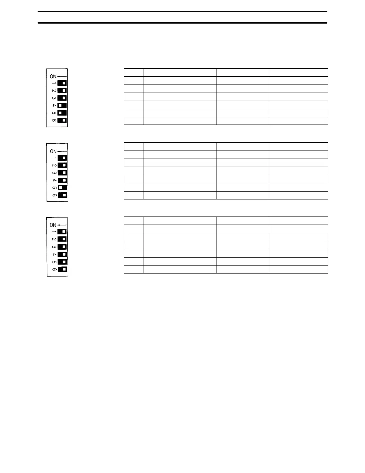
Set the DIP switch as described before for the various models of B7A Interface Units.
C200H-B7A22/12
Pin Function OFF ON
1 Transmission delay Standard (19.2 ms) High-speed (3 ms)
2 Transmission error process Hold status Reset Inputs
3 Input mode 16 inputs 15 inputs + error input
4 ERROR 1 indicator enable Disabled Enabled
5 ERROR 2 indicator enable Disabled Enabled
6 Not used. NA NA
C200H-B7A21
Pin Function OFF ON
1 Transmission delay Standard (19.2 ms) High-speed (3 ms)
2 Transmission error process Hold status Reset Inputs
3 Input mode 16 inputs 15 inputs + error input
4 ERROR indicator enable Disabled Enabled
5 Not used. NA NA
6 Not used. NA NA
C200H-B7A02
Pin Function OFF ON
1 Transmission delay Standard (19.2 ms) High-speed (3 ms)
2 Not used. NA NA
3 Not used. NA NA
4 Not used. NA NA
5 Not used. NA NA
6 Not used. NA NA
Transmission Delay
Pin 1 is used to set the transmission delay. The same delay is used for all words allocated to the Unit.
Set the transmission delay to match that of the B7A Link Terminal. A transmission error will occur if the same trans-
mission delay is not set.
The “3ms” indicator will be lit whenever the high-speed (3 ms) transmission delay is set.
Transmission Error Process
Pin 2 is used to turned ON to specify resetting input status when transmission errors occur. If pin 2 is turned OFF,
input status will be held when transmission errors occur.
The LOAD OFF indicator will be lit whenever pin 2 is turned ON.
Input Mode
Pin 3 is turned ON to specify use of only 15 inputs and the use of bit 15 as a Transmission Error Flag. If pin 3 is OFF,
16 normal inputs can be used.
The “15IN+ERR” indicator will be lit whenever pin 3 is turned ON.
ERROR Indicators
Pin 4 or pins 4 and 5 are turned ON to enable the ERROR, ERROR 1, and/or ERROR 2 indicators. These indica-
tors will not light even if a transmission error occurs if the corresponding pin is turned OFF.
Factory setting
(pins 4 and 5 ON)
Factory setting
(pin 5 ON)
Factory setting
(all pins OFF)