Appendix BSpecifications
185
Wiring
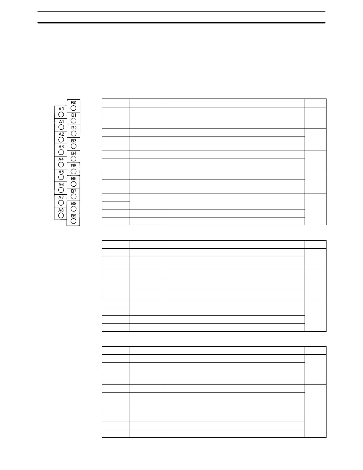
Terminal Names and Allocations
The use of the terminals depends on the model of the B7A Interface Unit. “m” indicates the first word allocated to
the Unit according to the I/O number setting and can be calculated as follows:
m = 030 + (2 x I/O number)
C200H-B7A22
Terminal Name Function Word
B0 SIG OUT1 Connect to SIG terminal on Output B7A Link Terminal.
m
B1 – OUT1 Connect to – power supply terminal on Output B7A Link
Terminal.
B2 SIG OUT2 Connect to SIG terminal on Output B7A Link Terminal.
m + 1
B3 – OUT2 Connect to – power supply terminal on Output B7A Link
Terminal.
B4 SIG IN1 Connect to SIG terminal on Input B7A Link Terminal.
m + 2
B5 – IN1 Connect to – power supply terminal on Input B7A Link
Terminal.
B6 SIG IN2 Connect to SIG terminal on Input B7A Link Terminal.
m + 3
B7 – IN2 Connect to – power supply terminal on Input B7A Link
Terminal.
B8
NC Not used. NA
A0 to A7
B9 +V Connect to + terminal on external power supply.
A8 –V Connect to – terminal on external power supply.
C200H-B7A21
Terminal Name Function Word
B0 SIG OUT1 Connect to SIG terminal on Output B7A Link Terminal.
m
B1 – OUT1 Connect to – power supply terminal on Output B7A Link
Terminal.
B2, B3 NC Not used. NA
B4 SIG IN1 Connect to SIG terminal on Input B7A Link Terminal.
m + 1
B5 – IN1 Connect to – power supply terminal on Input B7A Link
Terminal.
B6 to B8
NC Not used. NA
A0 to A7
B9 +V Connect to + terminal on external power supply.
A8 –V Connect to – terminal on external power supply.
C200H-B7A12
Terminal Name Function Word
B0 SIG IN1 Connect to SIG terminal on Input B7A Link Terminal.
m
B1 – IN1 Connect to – power supply terminal on Input B7A Link
Terminal.
B2, B3 NC Not used. NA
B4 SIG IN2 Connect to SIG terminal on Input B7A Link Terminal.
m + 1
B5 – IN2 Connect to – power supply terminal on Input B7A Link
Terminal.
B6 to B8
NC Not used. NA
A0 to A7
B9 +V Connect to + terminal on external power supply.
A8 –V Connect to – terminal on external power supply.