107
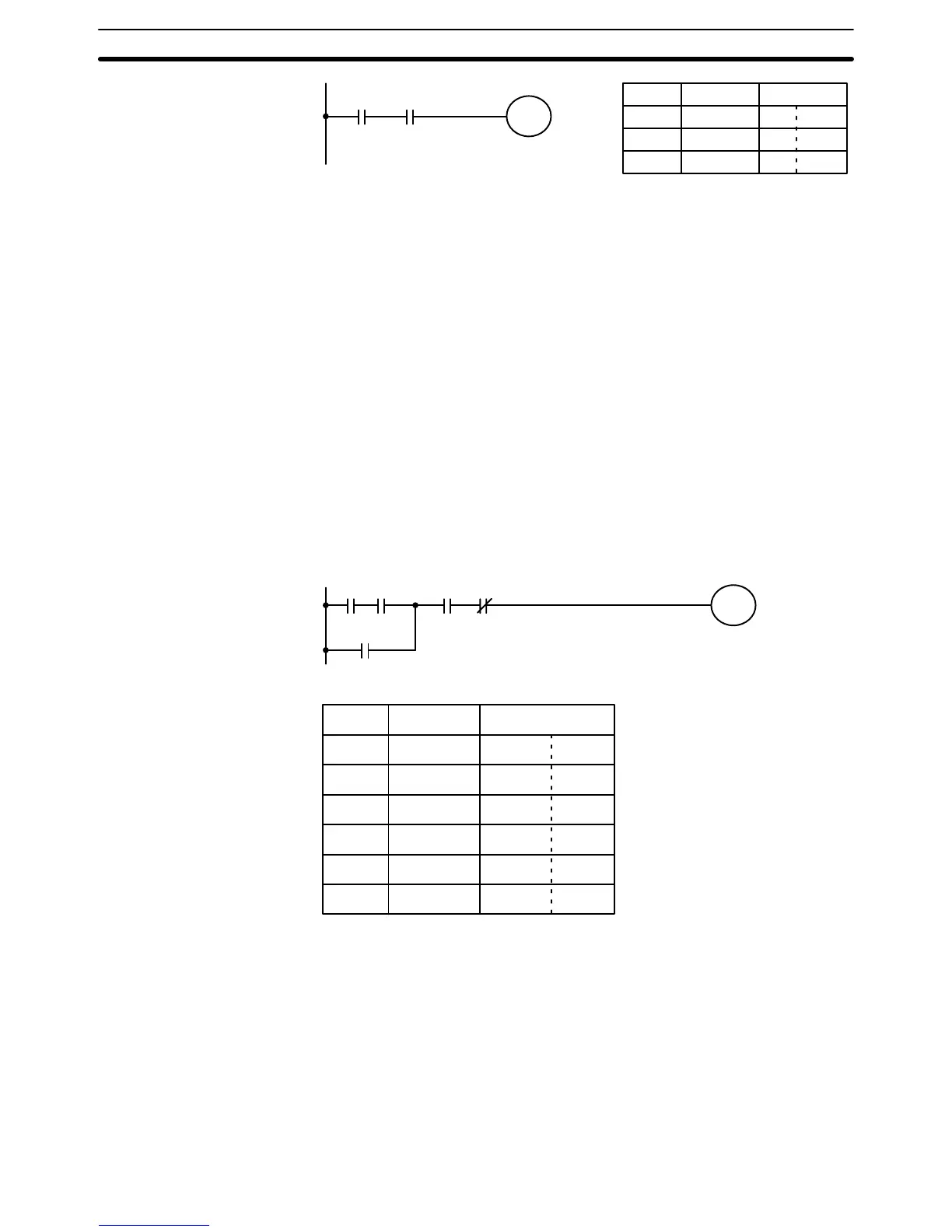
Address Instruction Data
0000 LD 0005
0001 AND 0006
0002 OUT 0505
0005 0006
0505
All instruction lines begin with a LD or LD NOT for the first condition. LD or
LD NOT is always used when an instruction line starts from the bus bar.
The address of the operand bit for LR (here, 0005) is written into the data
column next to LD. The data column will include any definers or bit operands
in the instruction word and the operands for all other words. Notice that the
data column is split into two. The left side is used to designate a data area or
# (to indicate a value as a constant) and the right side is used for the address
or numeric value of each.
The other condition in the ladder diagram corresponds to an AND. The oper-
and for AND is also a bit. In this case 0006, is placed on the right side. Re-
member, all data area addresses except for those for the IR or SR areas re-
quire designation with the appropriate prefix.
The final instruction in the diagram is OUT, which turns 0505 ON or OFF de-
pending on the execution condition. The operand bit 0505, is written in the
data column.
The following example requires both AND and OR instructions to convert, but
does so without requiring AND LD or OR LD. We provide the diagram and
corresponding mnemonic code for reference.
0000 0001 0002 0003
0200
0500
Address Instruction Data
0000 LD 0000
0001 AND 0001
0002 OR 0200
0003 AND 0002
0004 AND NOT 0003
0005 OUT 0500
7–2–3 Logic Block Instructions
When series of conditions lie in parallel to each other or when parallel groups
of conditions lie in series, it is impossible to convert them to mnemonic code
using only AND and OR operations. It is thus necessary to use the two logic
block instructions, AND LD and OR LD. These are introduced in
4–3–3 Logic
Block Instructions
.
As described in
4–3–3 Logic Block Instructions
, a logic block instruction logi-
cally combines execution conditions of two logic blocks or the execution con-
dition of a logic block and the execution condition produced by another logic
block instruction.
Converting to Mnemonic Code Section 7–2