67
0000 TIM 01 CNT 02
TIM 01
0001
CNT 00
0200
CP
R
TIM
0100
5.0 s
CNT 02
#0100
In the following example, CNT 01 counts the number of times the 1-second
clock pulse bit (1902) goes from OFF to ON. Here again, 0000 is used to
control when CNT is operating.
As the SV for CNT 01 is 700, the Completion Flag for CNT 02 turns ON when
1 second x 700 times, or 10 minutes and 40 seconds have expired. This
would result in 0202 being turned ON.
CP
R
CNT 01
#0700
0000 1902
0001
CNT 01
0202
The shorter clock pulses may not produce accurate timers because their
short ON times may not be read accurately for longer scan times. In particu-
lar the 0.02-second and 0.1-second clock pulses should not be used to cre-
ate timers with CNT.
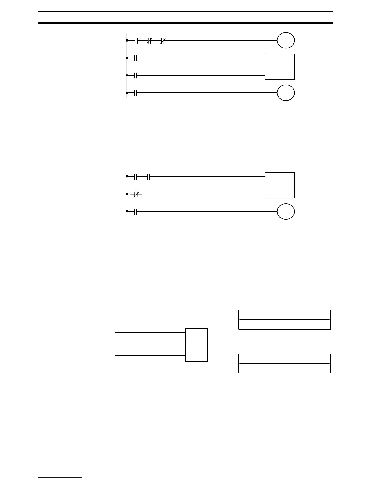
5–11–5 Reversible Counter – CNTR(12)
N: TC number
# (00 through 47)
Ladder Symbol
Definer Values
SV: Set value (word, BCD)
IR, HR, #
Operand Data Areas
II
DI
CNTR(12)
N
SV
R
Each TC number can be used as the definer in only one timer or counter in-
struction.
The CNTR(12) is a reversible, up-down circular counter, i.e., it is used to
count between zero and SV according to changes in two execution condi-
tions, those in the increment input (II) and those in the decrement input (DI).
The present value (PV) will be incremented by one whenever CNTR(12) is
executed with an ON execution condition for II and the execution condition
Note
Limitations
Description
Timer and Counter Instructions Section 5–11