24
3–4 SR Area
The SR area contains flags and control bits used for monitoring system op-
eration, accessing clock pulses, and signalling errors. SR area word ad-
dresses range from 18 through 19; bit addresses, from 1808 through 1907.
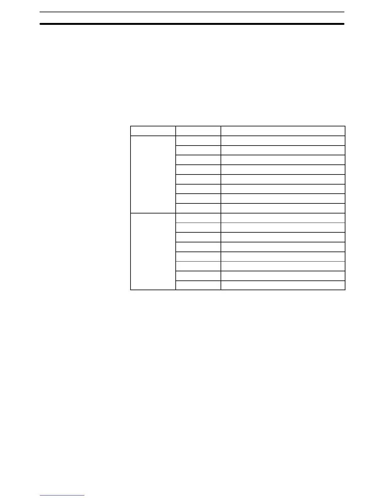
The following table lists the functions of SR area flags and control bits. Most
of these bits are described in more detail following the table.
Unless otherwise stated, flags are OFF until the specified condition arises,
when they are turned ON. Bits 1903 to 1907 are turned OFF when END is
executed at the end of each program scan, and thus cannot be monitored on
the Programming Console. Other control bits are OFF until set by the user.
Word Bit Function
18 08 Battery Alarm Flag
09 Scan Time Error Flag
10 High-speed Counter Reset
11 Always OFF Flag
12 Always OFF Flag
13 Always ON Flag
14 Always OFF Flag
15 First Scan Flag
19 00 0.1-second Clock Pulse
01 0.2-second Clock Pulse
02 1-second Clock Pulse
03 Error (ER) Flag
04 Carry (CY) Flag
05 Greater Than (GR) Flag
06 Equals (EQ) Flag
07 Less Than (LE) Flag
3–4–1 Battery Alarm Flag
SR 1808 turns ON if the voltage of the CPU backup battery drops. A voltage
drop can be indicated by connecting the output of this bit to an external indi-
cating device such as a LED. This bit can be used in programming to activate
an external warning for a low battery.
3–4–2 Scan Time Error Flag
SR 1809 turns ON if the scan time exceeds 100 ms. This bit is turned ON
when the scan time is between 100 and 130 ms. The PC will still operate but
timing may become inaccurate. The PC will stop operating if the execution
time exceeds 130 ms.
3–4–3 High-speed Drum Counter Reset
SR 1810 turns ON for one scan time when the hard reset signal (input 0001)
is turned ON.
3–4–4 Clock Pulse Bits
Three clock pulses are available to control program timing. Each clock pulse
bit is ON for the first half of the rated pulse time, then OFF for the second
half. In other words, each clock pulse has a duty factor of 1 to 1.
SR Area Section 3–4