32
the instruction is executed. This condition, which is either ON or OFF, is
called the execution condition for the instruction. All instructions except for
LOAD instructions have execution conditions.
The operands designated for any of the ladder instructions can be any bit in
the IR, SR, HR or TC area. This means that the conditions in a ladder dia-
gram can be determined by I/O bits, flags, work bits, timers/counters, etc.
Load and Output instructions can also use TR area bits, but they do so only
in special applications. Refer to
4–3–4 Branching Instruction Lines
for details.
What conditions correspond to what instructions is determined by the rela-
tionship between the conditions established by the instruction lines that con-
nect them. Any group of conditions that go together to create a logic result is
called a logic block. Although ladder diagrams can be written without actually
analyzing individual logic blocks, understanding logic blocks is necessary for
efficient programming and is essential when programs are to be input in mne-
monic code. Analyzing logic blocks in ladder diagrams and converting ladder
diagrams to mnemonic code is covered in
7–2 Converting to Mnemonic
Code
.
4–3–2 Ladder Instructions
The ladder instructions are those that correspond to the conditions on the
ladder diagram. Ladder instructions, either independently or in combination
with the logic block instructions described next, form the execution conditions
upon which all other instructions are executed.
The first condition that starts any logic block within a ladder diagram corre-
sponds to a Load or Load NOT instruction.
0000
0000
A Load instruction.
A Load NOT instruction.
When this is the only condition on the instruction line, the execution condition
for the instruction at the right is ON when the condition is ON. For the Load
instruction (i.e., a normal condition), the execution condition would be ON
when IR 0000 was ON; for the Load NOT instruction (i.e., an inverse condi-
tion), it would be ON when IR 0000 was OFF.
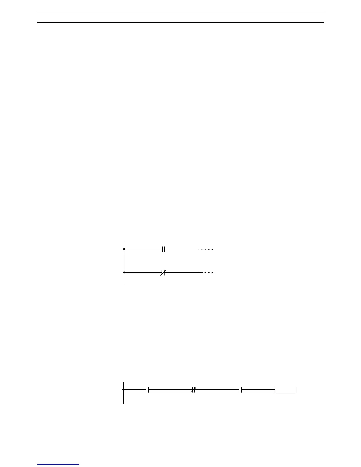
When two or more conditions lie in series on the same instruction line, the
first one corresponds to a Load or Load NOT instruction; the rest of the con-
ditions, to AND or AND NOT instructions. The following example shows three
conditions which correspond in order from the left to a Load, an AND NOT,
and an AND instruction.
0000 0100 HR 000
Instruction
The instruction at the right would have an ON execution condition only when
all three conditions are ON, i.e., when IR 0000 was ON, IR 0100 was OFF,
and HR 000 was ON.
Operand Bits
Logic Blocks
Load and Load NOT
AND and AND NOT
The Ladder Diagram Section 4–3