12
3–1 Introduction
Various types of data are required to achieve effective and correct control. To
facilitate managing this data, the PC is provided with various memory areas
for data, each of which performs a different function. The areas generally ac-
cessible by the user for use in programming are classified as data areas.
The other memory area is the Program Memory, where the user’s program is
actually stored.
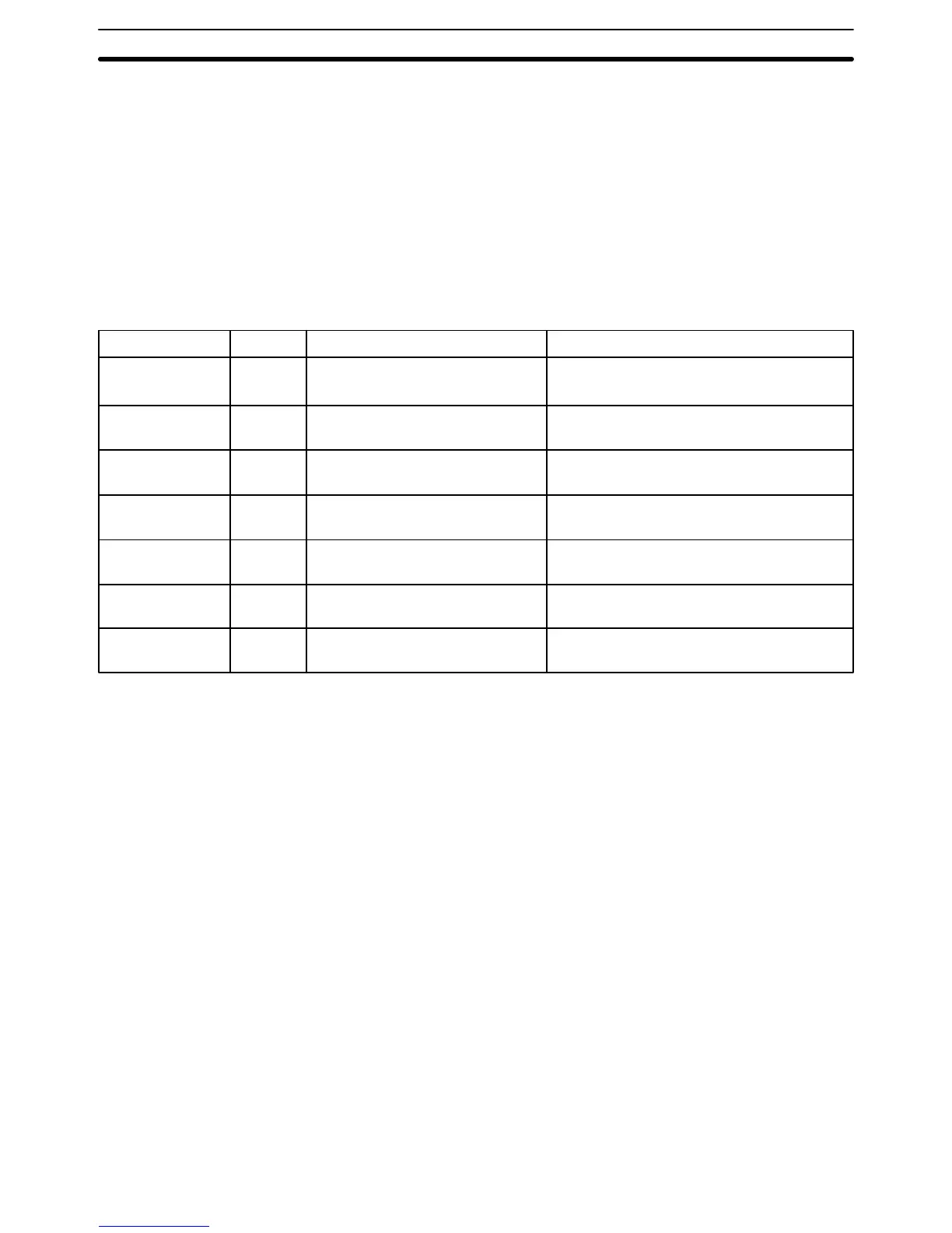
This section describes these areas individually and provides information that
will be necessary to use them. The name, acronym, range, and function of
each area are summarized in the following table. All but the last one of these
are data areas. All memory areas are normally referred to by their acronyms.
Area
Internal Relay
area
Special Relay
area
Data Memory
area
Holding Relay
area
Timer/Counter
area
Temporary Relay
area
Program Memory
Acronym
IR
SR
DM
HR
TC
TR
UM
Range
Words: 00 to 18 (right half)
Bits: 0000 to 1807
Words: 18 (left half) and 19
Bits: 1808 to 1907
DM 00 to DM 63
(words only)
Words: HR 0 to HR 9
Bits: HR 000 to HR 915
TC 00 to TC 47 (TC numbers are
used to access other information)
TR 00 to TR 07 (bits only)
UM: 1,194 words.
Function
Used to manage I/O points, control other bits,
timers, and counters, to temporarily store data.
Contains system clocks, flags, control bits, and
status information.
Used for internal data storage and manipulation.
Used to store data and to retain the data values
when the power to the PC is turned off.
Used to define timers and counters and to ac-
cess Completion Flags, PV, and SV for them.
Used to temporarily store execution conditions.
Contains the program executed by the CPU.
When some bits and words in certain data areas are not used for their in-
tended purpose, they can be used in programming as required to control
other bits. Words and bits available for use in this fashion are called work bits
and work words. Most, but not all, unused bits can be used as work bits.
Those that can be are specified by area in the remainder of this section. Ac-
tual application of work bits and work words is described in
Section 4 Pro-
gramming
.
Some data areas contain flags and/or control bits. Flags are bits that are
automatically turned ON and OFF to indicate status of one form or another.
Although some flags can be turned ON and OFF by the user, most flags can
be read only; they cannot be controlled directly.
Control bits are bits turned ON and OFF by the user to control specific as-
pects of operation. Any bit given a name using the word bit rather than the
word flag is a control bit, e.g., Restart Bits are control bits.
3–2 Data Area Structure
When designating a data area, the acronym for the area is always required
for any but the IR and SR areas. Although the acronyms for the IR and SR
areas are often given for clarity, they are not required and not input when
programming. Any data area designation without an acronym is assumed to
be in either the IR and SR area. Because IR and SR addresses run consecu-
tively, the word or bit addresses are sufficient to differentiate these two areas.
Work Bits and Words
Flags and Control Bits
Data Area Structure Section 3–2