47
5–4 Data Areas, Definer Values, and Flags
Each instruction is introduced with the ladder diagram symbol(s), the data
areas that can be used with any operand(s), and the values that can be used
for definers. With the data areas is also specified the operand names and the
type of data required for each operand (i.e., word or bit and, for words, hexa-
decimal or BCD).
Not all addresses in a specified data area are necessarily allowed in an oper-
and, e.g., if an operand requires two words, the last word in a data area can-
not be designated because all words for a single operand must be in the
same data area. Unless a limit is specified, any bit/word in the area can be
used. Specific limitations for operands and definers are specified in a
Limita-
tions
subsection. Refer to
Section 3 Memory Areas
for addressing conven-
tions and the addresses of flags and control bits.
The IR and SR areas are considered as separate areas and both are not
necessarily allowed for an operand just because one of them is. The boarder
between the IR and SR area can, however, be crossed for a single operand,
i.e., the last bit in the IR area may be specified for an operand that requires
more than one word as long as the SR area is also allowed for that operand.
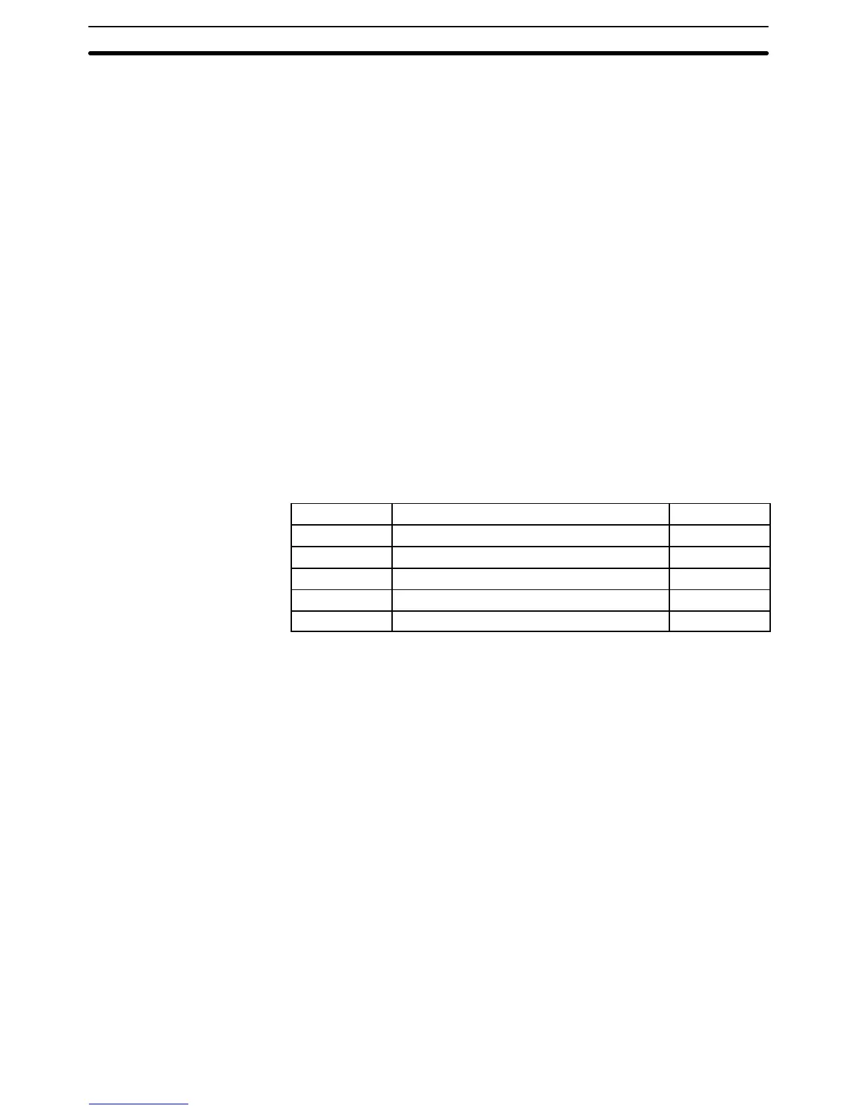
The
Flags
subsection lists flags that are affected by execution of the instruc-
tion. These flags include the following SR area flags.
Abbreviation Name Bit
ER Instruction Execution Error Flag 1903
CY Carry Flag 1904
EQ Equals Flag 1906
GR Greater Than Flag 1905
LE Less Than Flag 1907
ER is the flag most often used for monitoring an instruction’s execution.
When ER goes ON, it indicates that an error has occurred in attempting to
execute the current instruction. The
Flags
subsection of each instruction lists
possible reasons for ER being ON. ER will turn ON for any instruction if oper-
ands are not input within established parameters. Instructions are not exe-
cuted when ER is ON. A table of instructions and the flags they affect is pro-
vided in
Appendix D Error and Arithmetic Flag Operation
.
Although data area addresses are most often given as operands, many oper-
ands can be input and all definers are input as constants. The range in which
a number can be specified for a given definer or operand depends on the
particular instruction that uses it. Constants must also be input in the form
required by the instruction, i.e., in BCD or in hexadecimal.
5–5 Ladder Diagram Instructions
Ladder diagram instructions include ladder instructions and logic block in-
structions. Ladder instructions correspond to the conditions on the ladder
diagram. Logic block instructions are used to relate more complex parts of
the diagram that cannot be programmed with ladder instructions alone.
Note
Designating Constants
Ladder Diagram Instructions Section 5–5