102
Function
code
ConditionsExecution
time(
µs)
Instruction
30 ADD 233 When adding two words
352 When adding a TIM/CNT to a constant
31 SUB 237.5 When subtracting a word from a word
356.5 When subtracting a constant from a TIM/CNT
40 STC 16 Always
41 CLC 16 Always
61 HDM 734 Always
76 MLPX 212.5 Word, 1 digit (constant) —> word
288 Word, 4 digits (constant) —> word
355 TIM/CNT, 1 digit (TIM/CNT) —> word
431 TIM/CNT, 4 digits (TIM/CNT) —> word
77 DMPX 298.5 Word, 1 digit (constant) —> word
658.5 Word, 4 digits (constant) —> word
456 TIM/CNT, 1 digit (TIM/CNT) —> word
1,080 TIM/CNT, 4 digits (TIM/CNT) —> word
145 When shifting one word
743 When shifting 64 DM words
6–5 I/O Response Time
The I/O response time is the time it takes for the PC to output a control signal
after it has received an input signal. How long it takes to respond depends on
the scan time and when the CPU receives the input signal relative to the in-
put refresh period. The I/O response times for a PC not in a Link System are
discussed below. For response times for PCs with Link Systems, refer to the
relevant
System Manual.
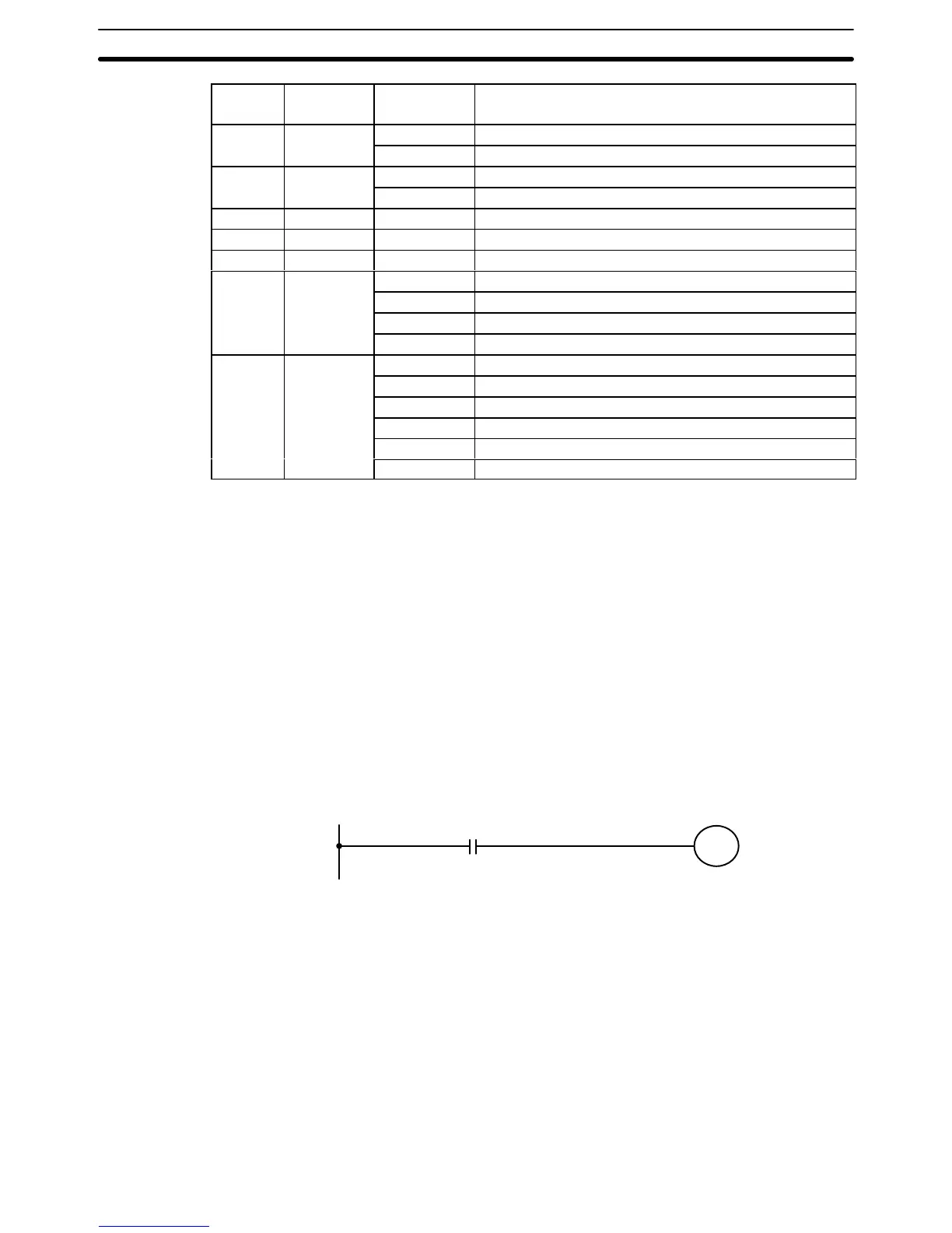
The minimum and maximum I/O response time calculations described below
are for the following, where 0000 is the input bit that receives the signal and
0500 is the output bit corresponding to the desired output point.
0000
0500
The PC responds most quickly when it receives an input signal just prior to
the input refresh period in the scan. Once the input bit corresponding to the
signal has been turned ON, the program will have to be executed once to
turn ON the output bit for the desired output signal and then the input refresh
and overseeing operations would have to be repeated before the output from
the output bit was refreshed. The I/O response time in this case is thus found
by adding the input ON-delay time, the scan time, the I/O refresh time, the
overseeing time, and the output ON-delay time. This situation is illustrated
below.
Minimum I/O Response
Time
I/O Response Time Section 6–5