31
branching lines, instruction lines. Along the instruction lines are placed condi-
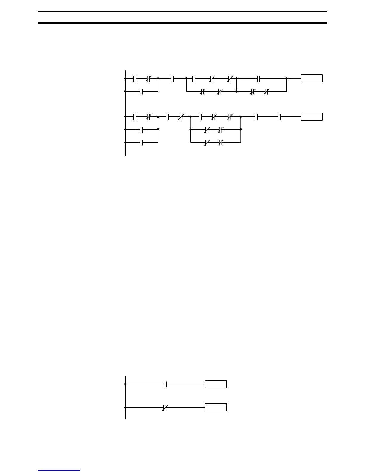
tions that lead to other instructions on the right side. The logical combinations
of these conditions determine when and how the instructions at the right are
executed. A simple ladder diagram is shown below.
0000 0315
Instruction
Instruction
0403
0001
HR 109 12031208 1200
0501 0502 0503 0504
1201
0100 0002
0010
0011
0003 HR 510 0007 TC 01 0515
1001 1002
0405
1005 1007
As shown in the diagram above, instruction lines can branch apart and they
can join back together. The vertical pairs of lines are called conditions. Con-
ditions without diagonal lines through them are called normal conditions and
correspond to a LOAD, AND, or OR instruction. The conditions with diagonal
lines through them are called inverse or NOT conditions and correspond to a
LOAD NOT, AND NOT, or OR NOT instruction. The number above each con-
dition indicates the operand bit for the instruction. It is the status of the bit
associated with each condition that determine the execution condition for fol-
lowing instructions. The function of each of the instructions that correspond
to a condition is described below. Before we consider these, however, there
are some basic terms that must be explained.
When displaying ladder diagrams with a GPC, a FIT, or LSS, a second bus
bar will be shown on the right side of the ladder diagram and will be con-
nected to all instructions on the right side. This does not change the lad-
der-diagram program in any functional sense. No conditions can be placed
between the instructions on the right side and the right bus bar, i.e., all in-
structions on the right must be connected directly to the right bus bar. Refer
to the
GPC, FIT,
or
LSS Operation Manual
for details.
4–3–1 Basic Terms
Each condition in a ladder diagram is either ON or OFF depending on the
status of the operand bit that has been assigned to it. A normal condition is
ON if the operand bit is ON; OFF if the operand bit is OFF. An inverse or
NOT condition is ON if the operand bit is OFF; OFF if the operand bit is ON.
Generally speaking, you use a normal condition when you want something to
happen when a bit is ON and an inverse condition when you want something
to happen when a bit is OFF.
Instruction
Instruction
0000
0000
Instruction is executed
when IR bit 0000 is ON.
Instruction is executed
when IR bit 0000 is OFF.
Normal condition
NOT condition
In ladder diagram programming, the logical combination of ON and OFF con-
ditions before an instruction determines the compound condition under which
Note
Normal and NOT
Conditions
Execution Conditions
The Ladder Diagram Section 4–3