10
2–1 Introduction
This section provides information on hardware aspects of P-type PCs that
are relevant to programming and software operation. These include indica-
tors on the CPU and basic PC configuration. This information is covered in
detail in the
Installation Guide
.
2–2 Indicators
CPU indicators provide visual information on the general operation of the
PC. Using the flags and other error indicators provided in the memory data
areas, although not a substitute for proper error programming, provides
ready confirmation of proper operation.
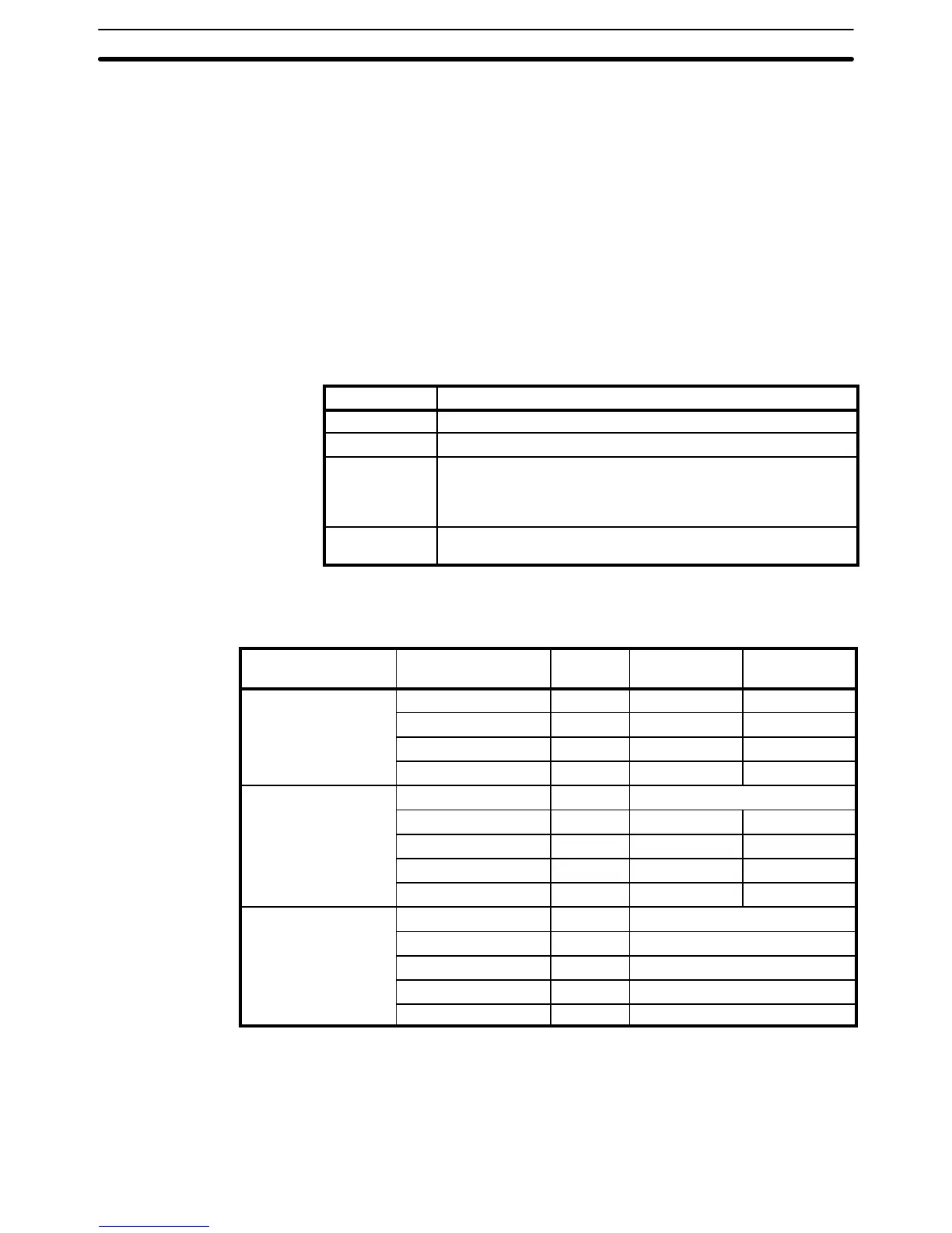
CPU indicators are located on the front right hand side of the PC adjacent to
the I/O expansion slot and are described in the following table.
Indicator Function
POWER Lights when power is supplied to the CPU.
RUN Lights when the CPU is operating normally.
ERR Lights when an error is discovered in system error diagnosis op-
erations. When this indicator lights, the RUN indicator will go off,
CPU operation will be stopped, and all outputs from the PC will
be turned OFF.
ALARM Lights when an error is discovered in system error diagnosis op-
erations. PC operation will continue.
2–3 PC Configuration
The Units from which P-type PCs can be built are shown below.
Unit type Name Words
occupied
Inputs
provided
Outputs
provided
CPU C20P 2 12 points 8 points
C28P 2 16 points 12 points
C40P 4 24 points 16 points
C60P 4 32 points 24 points
Expansion I/O Unit C4K 2 4 input points or 4 output points
C20P 2 12 points 8 points
C28P 2 16 points 12 points
C40P 4 24 points 16 points
C60P 4 32 points 24 points
Special I/O Units Analog Timer Unit 2 4 timer inputs
C4K Analog Input Unit 2 4 analog inputs
C1K Analog Input Unit 2 1 analog input
Analog Output Unit 2 1 analog output
I/O Link Unit 2 16 input and 16 output bits
Each PC is connected in series starting with a CPU and, if required, continu-
ing on with Expansion I/O or Special I/O Units. All other Units are connected
in series following the CPU and can be in any order desired except for the
I/O Link Unit, which must always come last. Up to five Units, including the
CPU can be connected as long as the total number of words occupied does
not exceed ten. Refer to
Section 3–3 IR Area
for configuration examples.
CPU Indicators
PC Configuration Section 2–3