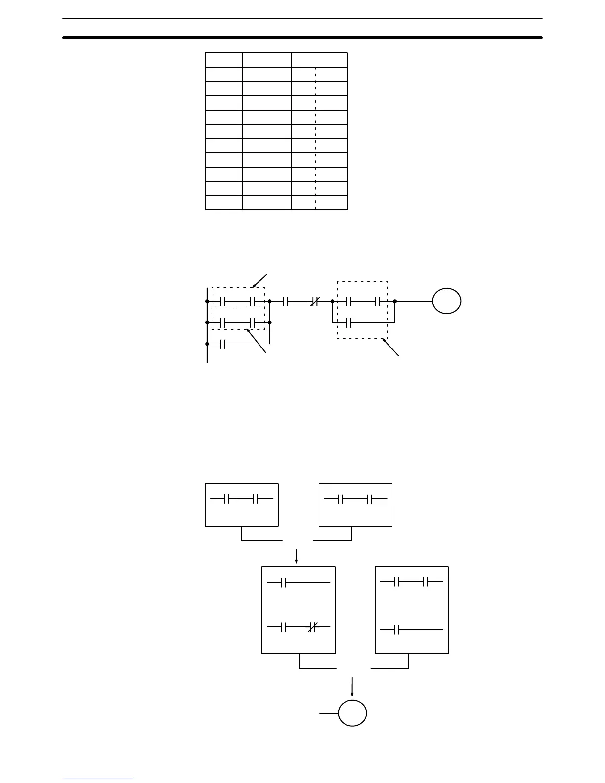
115
Address Instruction Data
0000 LD 0006
0001 AND 0007
0002 OR 0005
0003 AND 0003
0004 AND 0004
0005 LD 0001
0006 AND 0002
0007 OR LD ––
0008 AND 0000
0009 OUT 0505
Our last example may at first appear very complicated but can be coded us-
ing only two logic block instructions. The diagram appears as follows:
0000 0001
0505
0002 0003
0100 0101
0004 0005
0500
0006
Block c
Block b
Block a
The first logic block instruction is used to combine the execution conditions
resulting from blocks a and b, and the second one is used to combine the
execution condition of block c with the execution condition resulting from the
inverse condition assigned 0003. The rest of the diagram can be coded with
ladder instructions. The logical flow for this and the resulting code are shown
below.
0000 0001
0505
0002 0003
0100 0101
0004 0005
0500
0006
Block c
Block bBlock a
OR LD
LD 0000
AND 0001
LD 0500
LD 0002
AND NOT 0003
LD 0100
AND 0101
LD 0006
LD 0004
AND 0005
AND LD
Converting to Mnemonic Code Section 7–2