65
tion for CP and the execution condition was OFF for the last execution. If the
execution condition has not changed or has changed from ON to OFF, the
PV of CNT will not be changed. Counter is turned ON when the PV reaches
zero and will remain ON until the counter is reset.
CNT is reset with a reset input, R. When R goes from OFF to ON, the PV is
reset to SV. The PV will not be decremented while R is ON. Counting down
from SV will begin again when R goes OFF. The PV for CNT will not be reset
in interlocked program sections or for power interruptions.
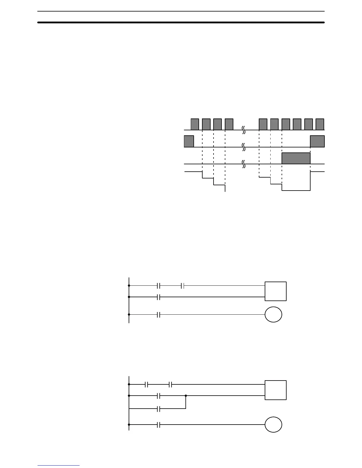
Changes in execution conditions, the Completion Flag, and the PV are illus-
trated below. PV line height is meant to indicate changes in the PV only.
Execution condition
on count pulse (CP)
Execution condition
on reset (R)
ON
OFF
ON
OFF
Completion Flag
ON
OFF
PV
SV
SV – 1
SV – 2
0002
0001
0000
SV
Program execution will continue even if a non-BCD SV is used, but the SV
will not be correct.
ER: SV is not in BCD.
In the following example, the PV will be decremented whenever both 0000
and 0001 are ON provided that 0002 is OFF and either 0000 or 0001 was
OFF the last time CNT 04 was executed. When 150 pulses have been
counted down (i.e., when PV reaches zero), 0205 will be turned ON.
0000
CP
R
CNT 04
#0150
0002
0001
0205
CNT 04
Here, 0000 can be used to control when CNT is operative and 0001 can be
used as the bit whose OFF to ON changes are being counted.
The above CNT can be modified to restart from SV each time power is
turned ON to the PC. This is done by using the First Scan Flag in the SR
area (1815) to reset CNT as shown below.
0000
CP
R
CNT 04
#0150
0002
0001
0205
CNT 04
1815
Precautions
Flags
Example 1:
Basic Application
Timer and Counter Instructions Section 5–11