72
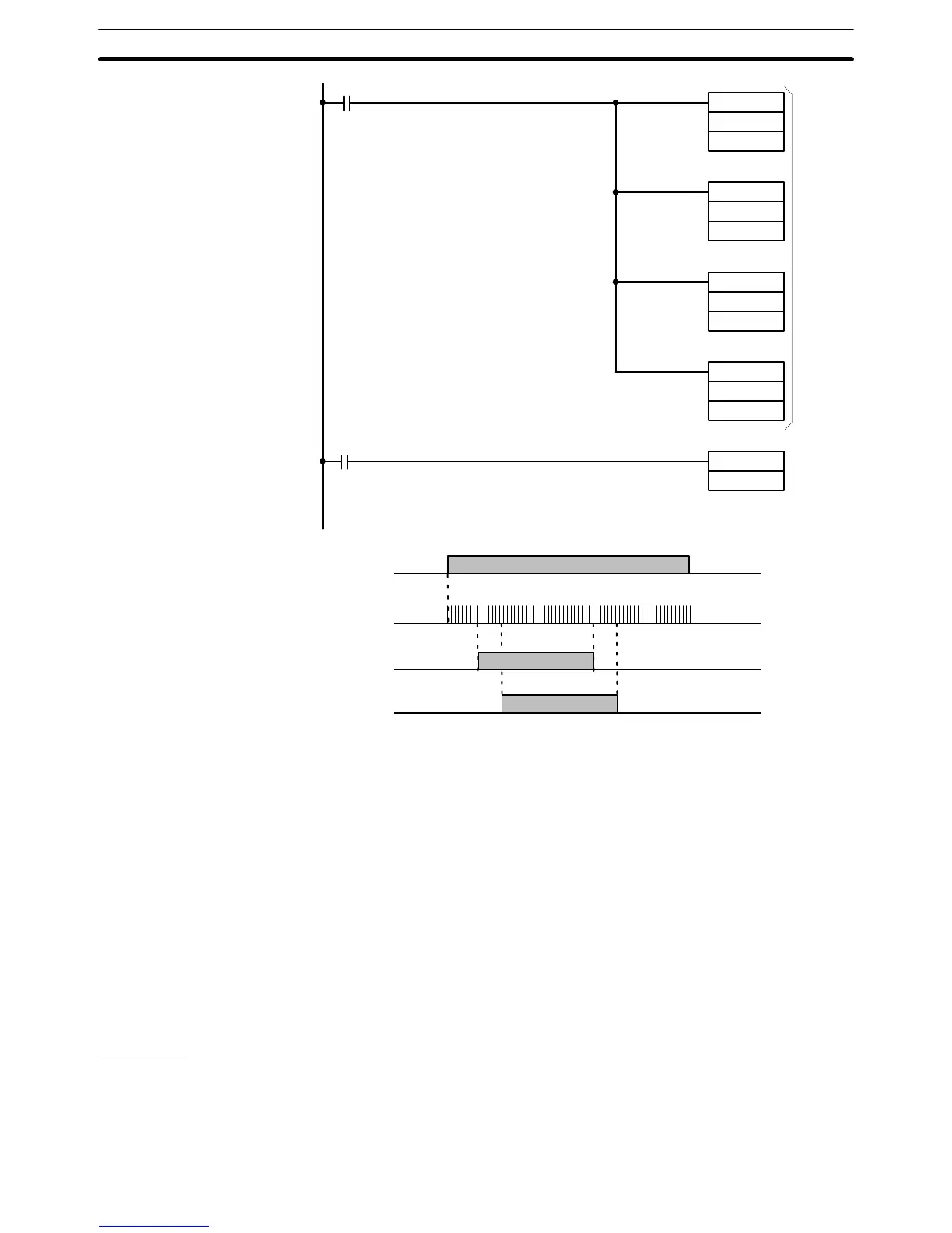
1813 (normally ON)
0002 (start input)
MOV(21)
#0200
DM 32
MOV(21)
#1500
DM 33
MOV(21)
#0600
DM 34
MOV(21)
#2000
DM 35
HDM(98)
05
Transfers
preset
value to
DM 32 to
35
Corresponding
result word is 05
Start input 0002
Output 0500
Output 0501
Count input 0000
200
600
1500
2000
The maximum response speed of the high-speed counter hardware is 2 kHz.
Note however that the start signal, reset signal (in the case of soft reset), and
corresponding outputs are all processed by software. Because of this, re-
sponse may be delayed by the scan time.
When programming the high-speed counter with the GPC, “00” is displayed
on each of the three lines below the instruction code (HDM(60)). Do not alter
the second and third lines; if they are not “00”, an error occurs when an at-
tempt is made to transfer the program from the GPC to the PC.
Do not program the high-speed counter between JMP and JME. The
high-speed counter can be programmed between IL and ILC. However, the
hard reset signal remains active, causing the corresponding output(s) to turn
ON or OFF, even when the IL condition is OFF.
Examples
The high-speed counter normally provides 16 output bits. If more than 16 are
required, the high-speed counter may be programmed more than once. In
the following program example, the high-speed counter is used twice to pro-
vide 32 output bits.
Response Speed
Precautions
Extending the Counter
Timer and Counter Instructions Section 5–11