79
The following example uses the 1-second clock pulse bit (1902) to so that the
execution condition produced by 0005 is shifted into a 3-word register be-
tween 10 and 12 every second.
I
P
SFT(10)
10
12
R
0005
1902
0006
The following program is used to control the status of the 17th bit of a shift
register running from IR 00 through IR 01 (i.e. bit 00 of IR 01). When the 17th
bit is to be set, 0204 is turned ON. This causes the jump for JMP(04) 00 not
to be made for that one scan and IR 0100 (the 17th bit) will be turned ON.
When 1280 is OFF (all times but the first scan after 0204 has changed from
OFF to ON), the jump is taken and the status of 0100 will not be changed.
I
P
R
SFT(10)
00
01
JME(05) 00
JMP(04) 00
0200
0100
DIFU(13) 1280
0201
0202
0203
0204
1280
1280
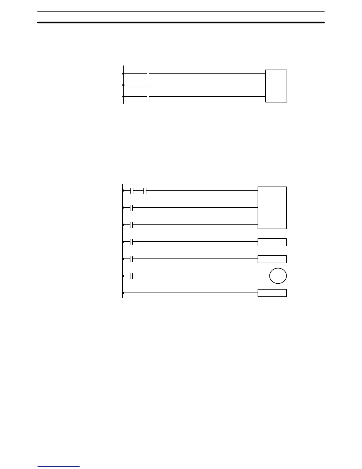
When a bit that is part of a shift register is used in OUT (or any other instruc-
tion that controls bit status), a syntax error will be generated during the pro-
gram check, but the program will execute properly (i.e., as written).
The following program controls the conveyor line shown below so that faulty
products detected at the sensor are pushed down a chute. To do this, the
execution condition determined by inputs from the first sensor (0001) are
stored in a shift register: ON for good products; OFF for faulty ones. Con-
veyor speed has been adjusted so that HR 003 of the shift register can be
used to activate a pusher (0500) when a faulty product reaches it, i.e., when
HR 003 turns ON, 0500 is turned ON to activate the pusher.
The program is set up so that a rotary encoder (0000) controls execution of
SFT(10) through a DIFU(13), the rotary encoder is set up to turn ON and
OFF each time a product passes the first sensor. Another sensor (0002) is
used to detect faulty products in the chute so that the pusher output and HR
003 of the shift register can be reset as required.
Example 1:
Basic Application
Example 2:
Controlling Bits in Shift
Registers
Example 3:
Control Action
Data Shifting Section 5–12