180
Simple Example of Use Section 4-1
6. Set the CSV tags.
7. Create (compile) the CSV tag file
Step 3 Setting up the Loop Control Board
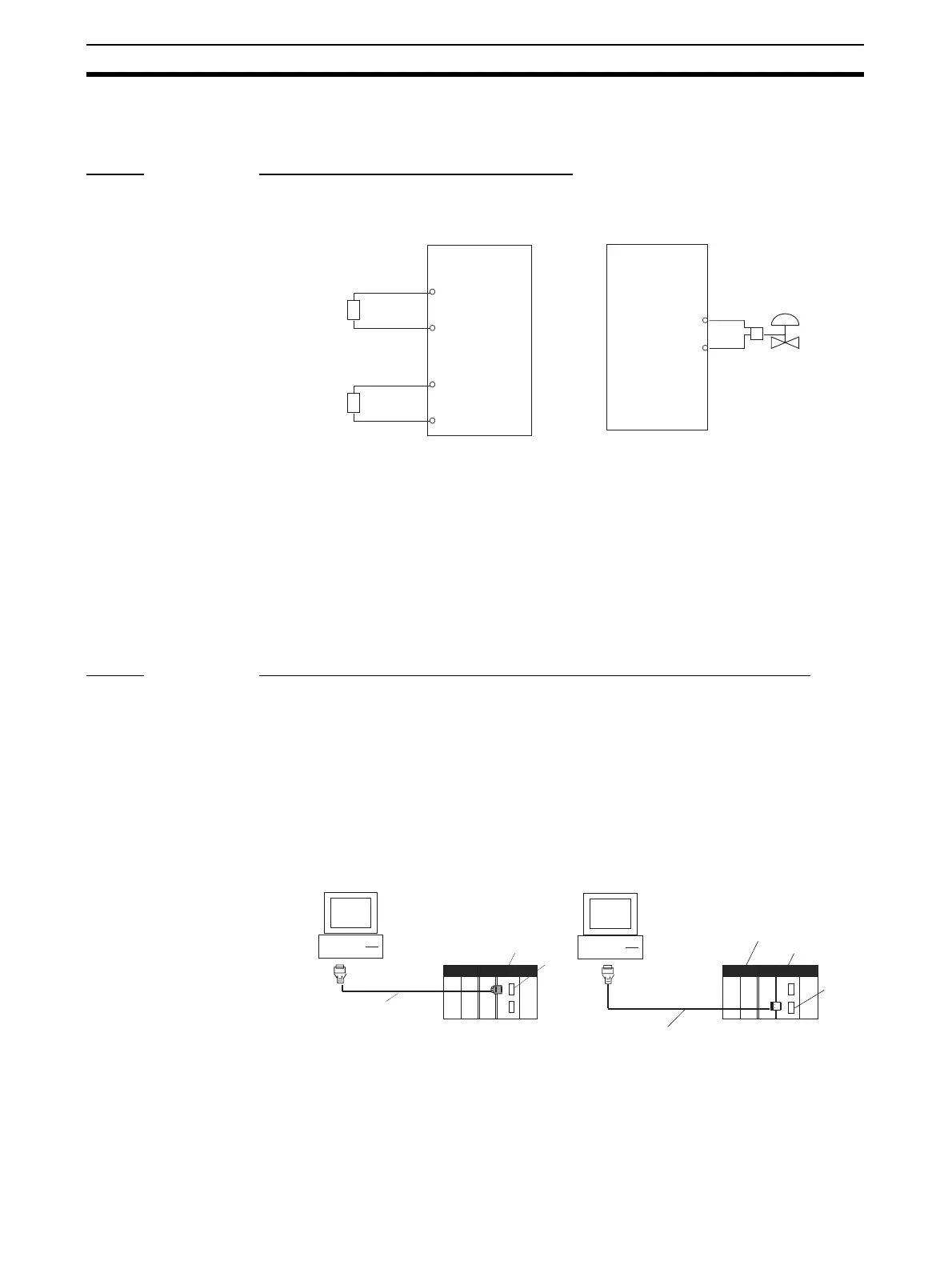
1. Mount the Loop Control Board, and wire the Analog Input Unit and Analog
Output Unit.
The Loop Control Board itself need not be wired.
2. Connect the Programming Devices.
3. Turn power ON to the PLC.
4. Prepare I/O tables using the Programming Devices.
5. Set the communications conditions of the serial communications port in
the PLC Setup using the Programming Devices if necessary.
6. Set the allocated Data Memory area of the Analog Input Unit or Analog
Output Unit using the Programming Devices.
Step 4 Downloading the Function Block Data to the Loop Controller
1,2,3... 1. Turn power OFF to the PLC.
2. Set the DIP switches on the front panel of the CPU Unit (SW4: ON when
using the peripheral port, OFF when using the RS-232C port).
3. Connect the CPU Unit to the Computer on which CX-Process Tool is run-
ning. (Connect to the active CPU Unit for CS1D-CPU@@P Process-control
CPU Units.)
4. Turn power ON to the PLC.
5. Set the network address (000) and node address (01) on CX-Process Tool.
(Settings - Network Settings)
6. Establish the Host Link connection on CX-Process Tool. (File - Initialize
Serial Port/F)
Analog Input Unit
Temperature
converter
4 to 20 mA
4 to 20mA
A2 Input 1 (
−
)
A5 Input 2 (
−
)
A1 Input 1 (
+
)
A4 Input 2 (
+
)
Differential
pressure
transmitter
Analog Output Unit
4 to 20 mA
Control valve
Output 1 (
+
) A4
Output 1 (
−
) A3
• Connection to peripheral port
(only Host Link connection is sup-
ported)
• Connection to RS-232C port (only
Host Link connection is supported)
Peripheral port
(9-pin male)
CS1 CPU Unit
Connector cable
CS1W-CN226/626
IBM PC/AT or compatible
RS-232C
port
IBM PC/AT or compatible
(9-pin male)
CS1 CPU Unit
Recommended cable XW2Z-200S-V
Loop Control Unit