49
Configuration of Instrumentation System Section 1-2
20.8 mA) are converted to 0.00 to 100.00 (-5.00 to 105.00)% before they are
processed by the Loop Controller.
These percentage unit values are scaled to engineering units values using
SCADA software.
!WARNING When the Field Terminal block is used for analog I/O, the unit number set on
the Field Terminal block must match the unit number set on the Analog I/O
Unit front panel. Otherwise, input/output (read/write) operations will be per-
formed by mistake on the data of another Special I/O Unit (having the unit
number set on the field terminals).
Note 1. With a User Link Table Read (Rd) tag, the word data is interpreted as dec-
imal data and the user can freely specify the range that determines which
value is equivalent to 0% and which value is equivalent to 100%. For ex-
ample, if a range of 0 to 4,000 (0000 to 0FA0 Hex) is specified for inputs
from the CPU Unit, I/O memory word contents between 0000 and 0FA0 will
be converted to the range 0.00 to 100.00% and then input.
2. Conversely, with a User Link Table Write (Wr) tag, the user can specify the
value to which 0% will be converted and the value to which 100% will be
converted. For example, if a range of 0 to 4,000 (0000 to 0FA0 Hex) is
specified for outputs to the CPU Unit, outputs in the range 0.00 to 100.00%
will be converted to values between 0000 and 0FA0 and then output to I/O
memory words in the CPU. In the SCADA software, these percentage units
scale the output to the desired industrial units.
Input and Output of
Contacts
The Loop Controller can exchange contacts (bit data) with the Basic I/O Unit
or the Contact I/O Unit of the Special I/O Unit. In data exchange with these
Units, use the DI Terminal and DO Terminal blocks on the Field Terminal block
having the corresponding number of contact I/O points.
On the DI Terminal and DO Terminal blocks, set the leading allocated address
of the Contact I/O Unit for performing contact I/O operations.
Note In the case of a contact I/O Field Terminal block, select the function
block not according to Unit model but according to the number of
contact I/O points.
Note 1. When user link tables are used to exchange data with the Contact I/O Unit
allocated CIO Area, data exchange functionally is the same as when the
Field Terminal blocks are used to perform data exchange.
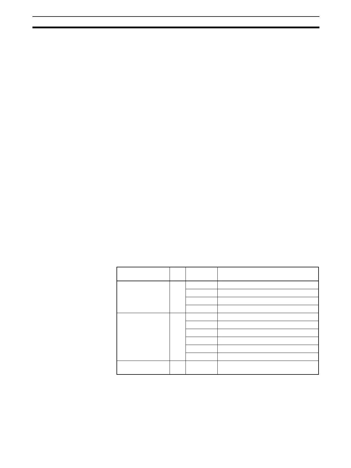
Unit I/O Number of
points
Function block
Contact Input Unit I 8 DI 8-point Terminal (Block Model 501)
16 DI 16-point Terminal (Block Model 502)
32 DI 32-point Terminal (Block Model 503)
64 DI 64-point Terminal (Block Model 504)
Contact Output Unit O 5 DO 5-point Terminal (Block Model 511)
8 DO 8-point Terminal (Block Model 512)
12 DO 12-point Terminal (Block Model 513)
16 DO 16-point Terminal (Block Model 514)
32 DO 32-point Terminal (Block Model 515)
64 DO 64-point Terminal (Block Model 516)
Contact I/O Unit I/O 16/16 DI 16-point/DO 16-point Terminal (Block
Model 518)