5-1SectionUnit Setup Area
61
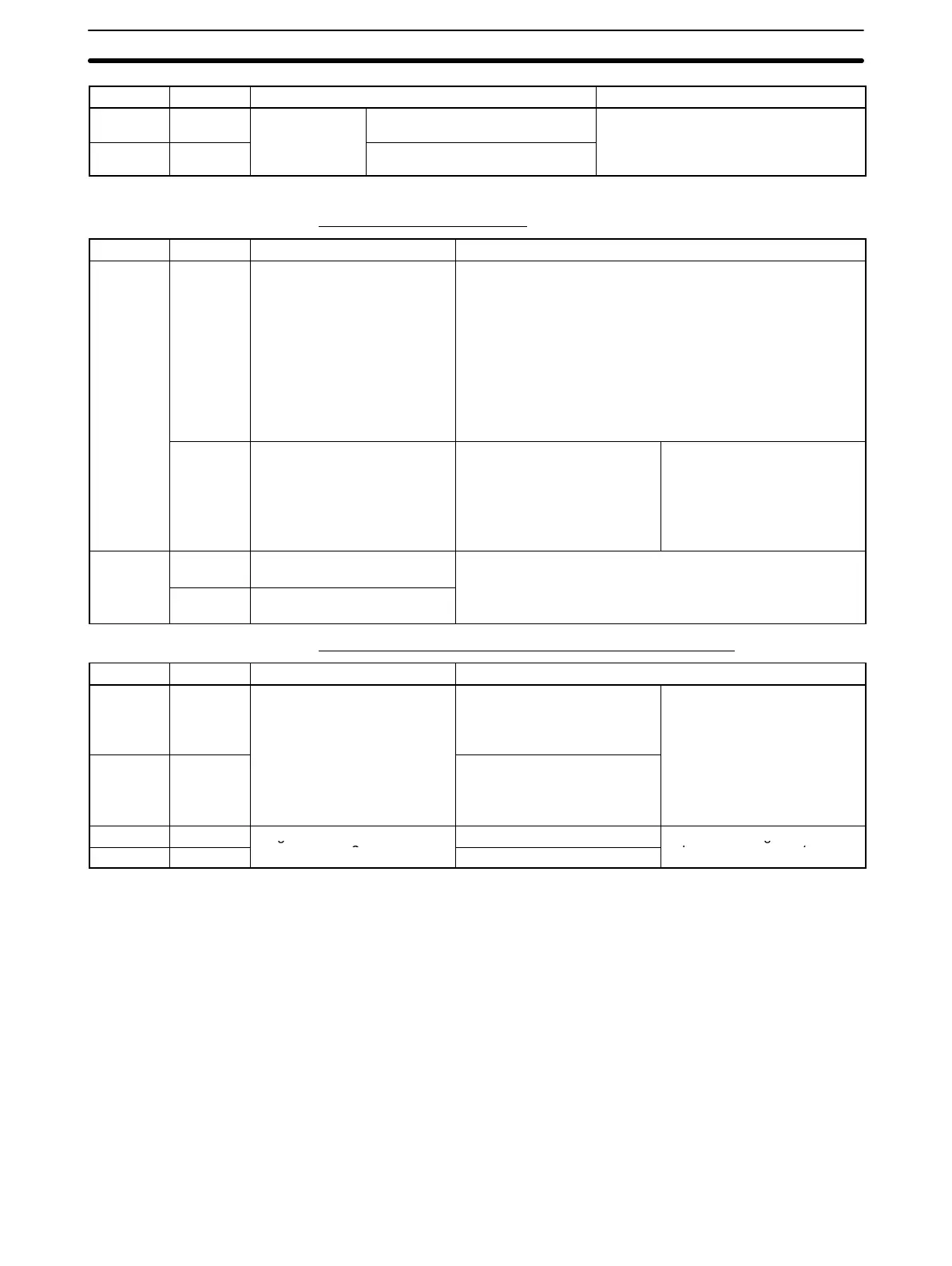
Address DetailsFunctionBits
DM 6611 00 to 15
Maximum ring
counter value
Rightmost 4 digits
As above.
DM 6612 00 to 15
u
u
for high-speed
counter 2
Leftmost 4 digits
Settings for Pulse Outputs (CS1W-HCP22 Only)
Settings Enabled at Startup
Address Bits Function Details
DM 6613
00 to 07 Pulse output 1 operation
mode
00 Hex: Relative pulse output (No. of output pulses = pulse
output value)
01 Hex: Linear-mode absolute pulse output (No. of output
pulses = |PV of pulse output – target pulse amount)|
02 Hex: Ring-mode absolute pulse output (As above. If the
ring set value is exceeded, the count value returns to 0000
0000 Hex.)
03 Hex: Electronic cam mode (output with absolute position
specification)
04 Hex: One-shot pulse output
05 Hex: Output pulse counter timer
08 to 15 Pulse output 1 clock
frequency
00 Hex: 25 MHz
01 Hex: 6.25 MHz (25/4)
02 Hex: 1.5625 MHz (25/16)
03 Hex: 390.625 kHz (25/64)
Pulse output frequency
ranges:
00 Hex: 400 Hz to 200 kHz
01 Hex: 100 Hz to 100 kHz
02 Hex: 25 Hz to 50 kHz
03 Hex: 6 Hz to 20 kHz
DM 6614
00 to 07 Pulse output 2 operation
mode
Same as for pulse output 1.
08 to 15 Pulse output 2 clock
frequency
Settings Enabled at Startup and when Operation Starts
Address Bits Function Details
DM 6630 00 to 15
Ring set value for pulse
output counter 1
Rightmost 4 digits
Used to set the maximum ring
value when the pulse output 1
operation mode is set to Ring
Mode for absolute pulse
DM 6631 00 to 15 Leftmost 4 digits
output (bits 00 to 07 in DM
6613).
Range: 0000 0001 to FFFF
FFFF Hex (8 digits)
DM 6632 00 to 15
Ring set value for pulse
Rightmost 4 digits
Same as for ring set value for
DM 6633 00 to 15
output counter 2
Leftmost 4 digits
pulse output counter 1.