Please connect V430-W8□ to the I/O connector (M12 plug) and connect it to power supply etc.
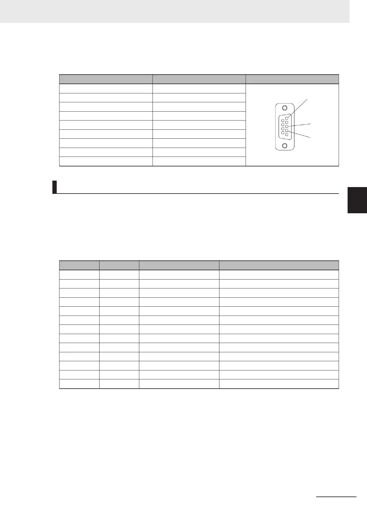
RS-232C (D-sub 9 Pin Female Connector)
Pin No. Signal Name Pin Layout Diagram
1 ‐
2 HOST_RxD
3 HOST_TxD
4 ‐
5 0V
6 ‐
7 ‐
8 ‐
9 ‐
Using the RS-232C Signal on I/O cable (V430-W8□).
RS-232C communication is possible by combining the signal for RS-232C communication
(HOST_RxD, HOST_TxD) coming from the I/O cable (V430-W8□) with the RS-232C signal of the de-
vice it is connected to.
(If the V430-W8□ is connected to the M12 plug of the V430-W2-3M, the RS-232C signal on the V430-
W8□ cannot be used.)
I/O Cable Connection Diagram (All V430-W8)
Wire color Pin No. Signal Name Function
Brown 2 24V Power supply
Blue 7 0V GND
Red 8 COM_IN Common Input Signals (Input Common)
Red / Black 12 COM_OUT Common Output Signals (Output Common)
White 1 TRIG Read Trigger Input (Trigger)
Black 9 HOST_RxD Receive Data (RS-232(Host) RxD)
Purple 10 HOST_TxD Transmit Data (RS-232(Host) TxD)
Gray 5 OUTPUT 1 (Output 1)
Gray / Red 11 OUTPUT 2 (Output 2)
Pink 6 OUTPUT 3 (Output 3)
Green 3 DEFAULT (Default)
Yellow 4 NEW MASTER (New Master)
None ‐ ‐ (Shield)
5 Controlling Operation and Data Output with RS-232C
5 - 3
V430-F Series Autofocus Multicode Reader User Manual for Communication Settings
5-1 Controlling Operation and Data Output with RS-232C
5
5-1-2 RS-232C Wiring

 Loading...

