3-1-6
Status and Control Signals for Each Input and Output Assembly
The V430-F has the following types of Input Assemblies.
(1) Small Input Assembly
(2) Large Input Assembly
(3) MXL/SLC Input Assembly
(4) 1 Decode Input Assembly
(5) 4 Decode Input Assembly
(6) N Decode Input Assembly
The Status signals are as follows.
These signals are controlled automatically based on the status of the code reader
.
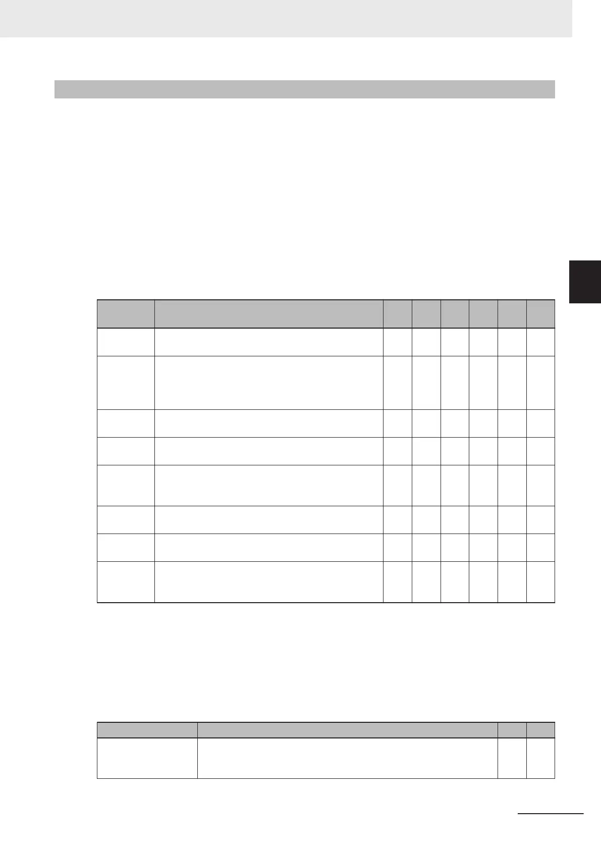
○: Verifiable ×: Not Verifiable
Status Sig-
nal
Description (1) (2) (3) (4) (5) (6)
InReadCy-
cle
While in Read Cycle, this bit is set to 1.
× ○ × × × ×
Trigger Ac-
knowledged
This bit becomes 1
when the Trigger bit from the Out-
put Assembly is received.
When the Trigger bit is OFF, Trigger Acknowledged al-
so becomes 0.
× × ○ ○ ○ ○
Exposure
Done
During exposure, this bit is set to 1.
When Exposure is done, this bit becomes 0.
× × ○ ○ ○ ○
Decoding
When reader is decoding image, this bit is set to 1.
When the decode is completed, this bit becomes 0.
× × ○ ○ ○ ○
Data is
Ready
When the data from Read Cycle Report and Data Cy-
cle Report is confirmed, this bit becomes 1.
When the next Read starts, this bit becomes 0.
×
× ○ ○ ○ ○
Read Cycle
Pass
On Good Read (or Match if Matchcode enabled), bit
becomes 1. When next Read starts, bit becomes 0.
× × ○ ○ ○ ○
Read Cycle
Fail
On No Read (or Mismatch if Matchcode enabled), bit
becomes 1. When next Read starts, bit becomes 0.
× × ○ ○ ○ ○
Decode
Data
This field stores the Read string. When additional in-
formation such as Print Quality Grading Standard is
set, it is stored following the Read string.
○ ○ ○ ○ ○ ○
The following are the two V430-F Output Assembly types.
(1) Output Assembly
(2) Output Assembly (Legacy)
The Control Signals are as follows.
They can be controlled by the user at an arbitrary timing.
○: V
erifiable
×: Not V
erifiable
Control Signal Description (1) (2)
Trigger Executes Read. The code reader recognizes this bit changing from 0 to
1 as the rising edge of the trigger and its change from 1 to 0 as the fall-
ing edge of the trigger.
○ ○
3 Controlling Operation and Data Output with Ethernet
3 - 11
V430-F Series Autofocus Multicode Reader User Manual for Communication Settings
3-1 Controlling Operation and Data Output with Ether-
Net/IP
3
3-1-6 Status and Control Signals for Each Input and Output Assembly

 Loading...

