3-1-9
Accessing the NJ-series Controller Communication Areas using
V
ariables
With an NJ-series, accessing the I/O memory allocated to each communication area can be done with
the user program with the use of variables.
Here is an example of using the MXL/SLC Input Assembly (102) and Output Assembly (197) for that
purpose.
For more detailed information about the data structure of each Assembly, please refer to
A-2 EtherNet/IP Detailed Specifications on page A - 3
Access using Network Variables
Create user-defined variables that match the structures of the communications areas of the Sensor.
Use the Sysmac Studio to define the variables.
For how to use Sysmac Studio, please refer to Sysmac Studio Version1 Operation Manual
(
W504
)
.
1 Defining the Data Types of the Variables
Define data types for variables that match the structures of the communications areas.
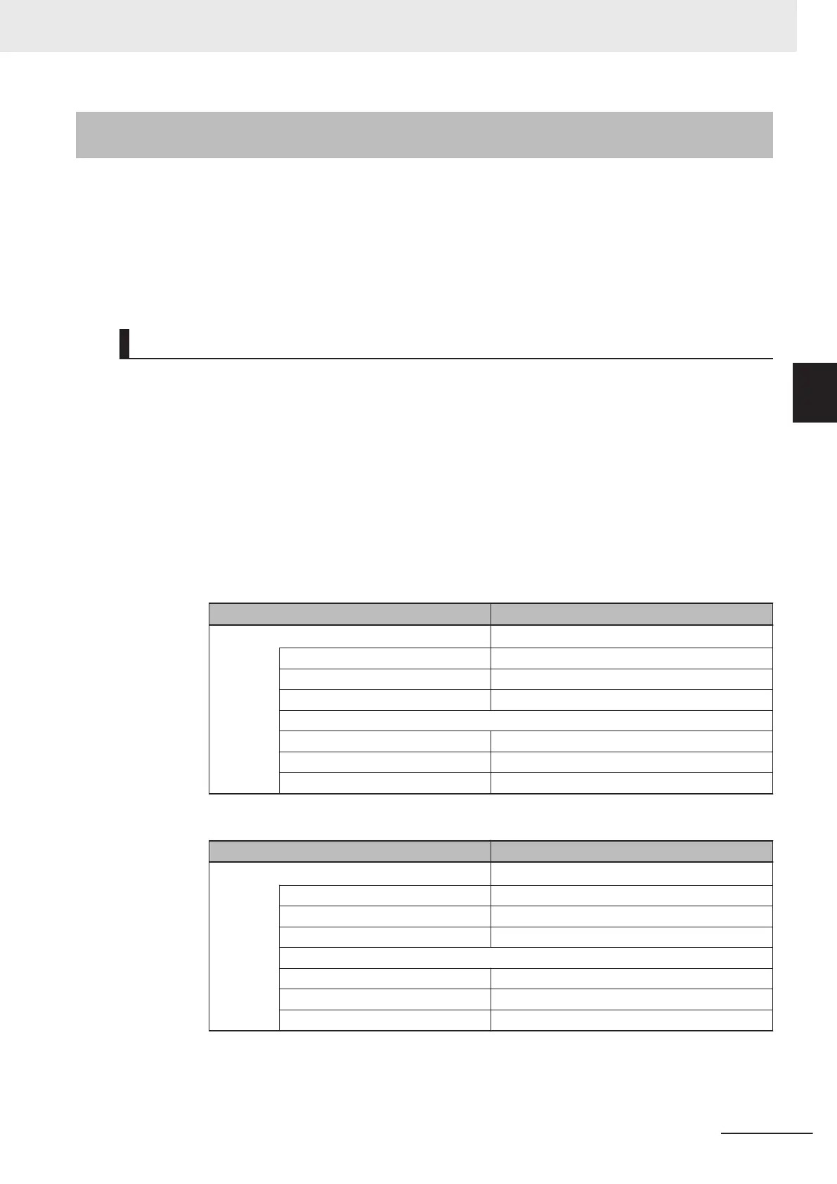
(1) Defining a Data Type for Control Signal Access
First, define a BOOL array data type to access the control signals and status signals.
Here, we define the Data types, COMMAND and Device_Status.
Control Signal
Data Name Data Type
COMMAND ARRAY[0..31]OF BOOL
Run_Mode BOOL
Trigger BOOL
Enable_Matchcode BOOL
…
Output_2 BOOL
Output_3 BOOL
Reserved ARRAY[0..17]OF BOOL
Status Signals
Data Name Data Type
Device_Status ARRAY[0..31]OF BOOL
Online BOOL
Trigger_Acknowledged BOOL
Exposure_Done BOOL
…
Output2_Status BOOL
Output3_Status BOOL
Reserved ARRAY[0..10]OF BOOL
(2) Defining Data Types for Communications Area Access
Data types are defined according to the communication area to access, with one data type
for Output Area and another data type for Input Area.
Here, there are two Data types defined, S_EIPOutput197 and S_EIPInput102.
3 Controlling Operation and Data Output with Ethernet
3 - 15
V430-F Series Autofocus Multicode Reader User Manual for Communication Settings
3-1 Controlling Operation and Data Output with Ether-
Net/IP
3
3-1-9 Accessing the NJ-series Controller Communication Areas using Variables

 Loading...

