3-1-3
Communication Flow Between PLC and Code Reader
(1) The PLC (User) changes the Trigger bit assigned to the memory area (Output Field) of the PLC in
advance from OFF to ON.
(2) When the Trigger bit from the PLC is ON, the code reader executes a Read process.
(3) After the code reader's Read process is complete, it then stores its Read data in the specified
memory area (Input Field) on the PLC.
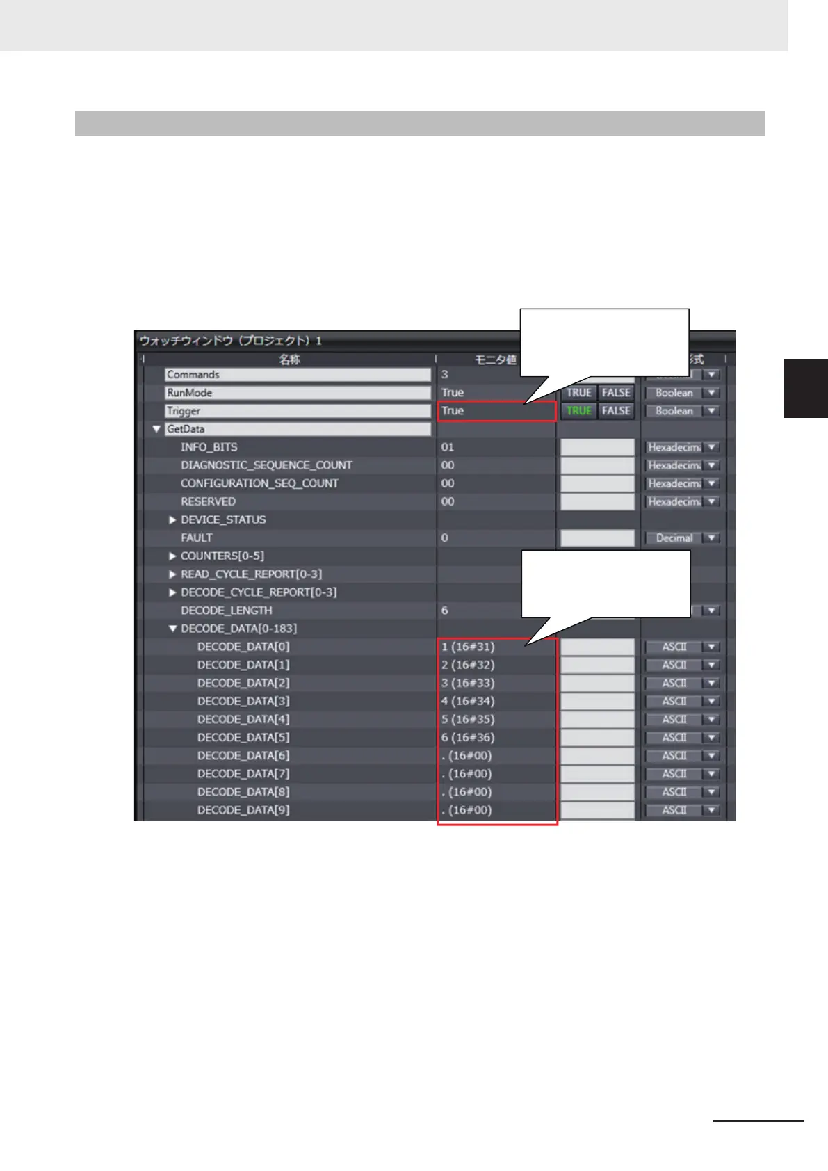
[Output Data Example]
Character string is output to
DECODE DATA Area
Trigger bit is True
3 Controlling Operation and Data Output with Ethernet
3 - 5
V430-F Series Autofocus Multicode Reader User Manual for Communication Settings
3-1 Controlling Operation and Data Output with Ether-
Net/IP
3
3-1-3 Communication Flow Between PLC and Code Reader

 Loading...

