3-2-3
Communication Settings (Serial (TCP))
Network settings on the Code Reader
Set the IP address on the code reader to match the network settings of the PLC or other external de-
vice.
• WebLink - Setup - Gear Icon
- Advanced Settings - Communications - Ethernet
1 Set Ethernet to Enabled.
2 Set the IP Address and Subnet mask according to the network settings of the PLC or other
external device.
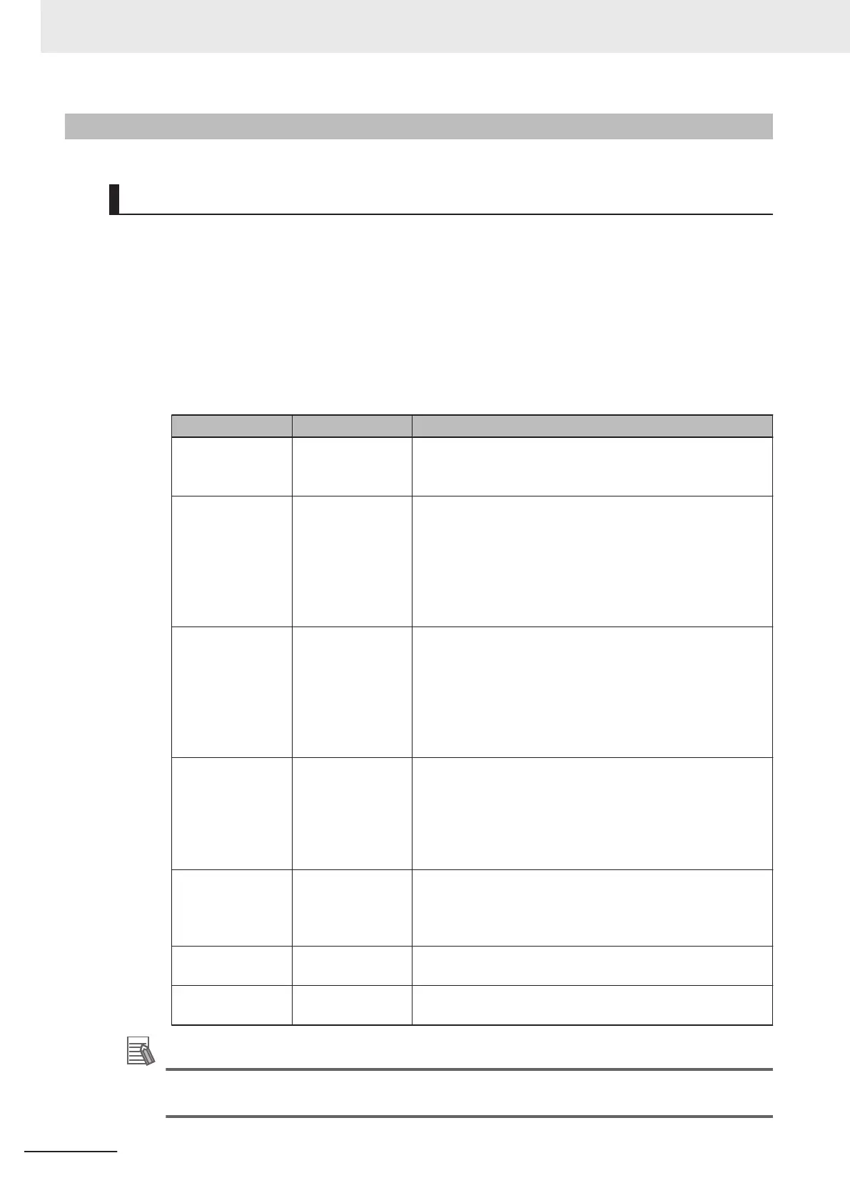
Setting Item Setting Value Description
Ethernet
• Enabled
(default)
• Disabled
Select whether to enable all, some, or none of the various
Ethernet protocols, (Serial (TCP)), EtherNet/IP, PROFINET).
IP Address a.b.c.d
a: 0 to 255
b: 0 to 255
c: 0 to 255
d: 0 to 255
(Default:
192.168.188.2)
Enter the IP address of the Code Reader
Subnet a.b.c.d
a: 0 to 255
b: 0 to 255
c: 0 to 255
d: 0 to 255
(Default:
255.255.0.0)
Input the subnet mask address.
Gateway a.b.c.d
a: 0 to 255
b: 0 to 255
c: 0 to 255
d: 0 to 255
(Default: 0.0.0.0)
If a Gateway is used, enter the gateway address. If a Gate-
way is not used, use the default value 0.0.0.0.
IP Address Mode
• Fixed
(default)
• DHCP
In Fixed mode, the code reader uses a user-defined IP ad-
dress.
In DHCP mode, the code reader acquires its IP address,
subnet, and gateway from the DHCP server
.
TCP Port 1 1024 to 65536
(Default: 2001)
Enter one of the two TCP port numbers for communication
with the code reader over Serial (TCP).
TCP Port 2
1024 to 65536
(Default: 2003)
Enter one of the two TCP port numbers for communication
with the code reader over Serial (TCP).
Additional Information
Through the use of two TCP ports at the same time, it is possible for the V430-F to
communicate over Serial (TCP) with two different external devices.
3 Controlling Operation and Data Output with Ethernet
3 - 30
V430-F Series Autofocus Multicode Reader User Manual for Communication Settings

 Loading...

