Control Signal Description (1) (2)
New Master When this bit is ON, the next Read result is registered as the Master
Symbol.
○ ○
3-1-7
Timing Charts by Assembly Type
Read is executed by the Read (TRIG) Signal.
The timing signal at completion of storing the Read data to PLC data memory differs by the Input
Assembly type.
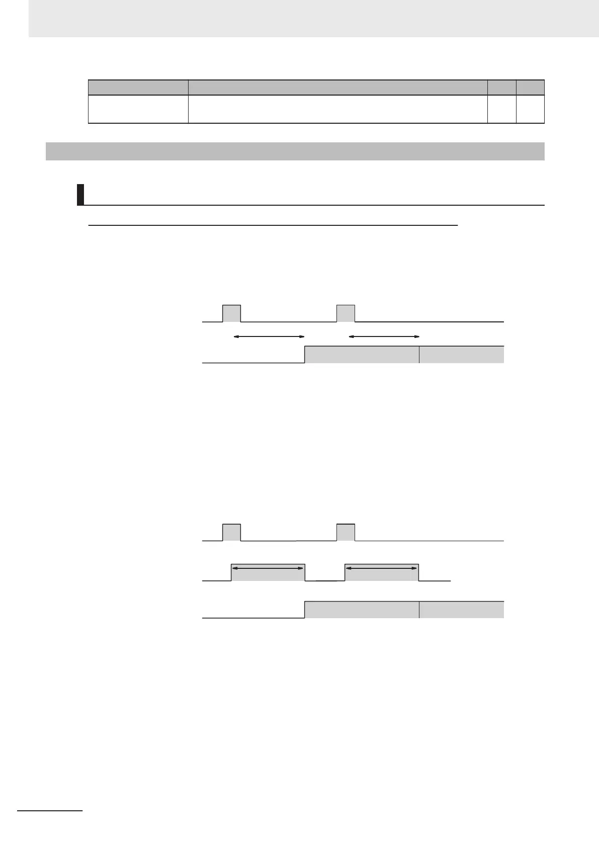
Small Input Assembly (100)
It does not correspond to the Timing Signal for storing Read data.
Trigger
OFF
ON
Decode Date
Executes read.
Read data
In Read Cycle In Read Cycle
Read data
Executes read.
(1) Reading starts at the rising edge of the Trigger.
(2) At the end of reading, the read data is stored in Decode Data.
Large Input Assembly (101)
It is output at the timing of the Device Status - InReadCycle bit turning from ON → OFF.
Trigger
OFF
ON
Decode Date
Executes read.
Read data
Read data
Executes read.
InReadCycle
OFF
ON
In Read Cycle
In Read Cycle
ChecktoconfirmifReadisinprogress
(1) Reading starts at the rising edge of the Trigger.
(2) At start of Read, InReadCycle turns ON and Trigger turns OFF.
(3) At end of Read, the Read data is stored in Decode Data and InReadCycle turns OFF.
3 Controlling Operation and Data Output with Ethernet
3 - 12
V430-F Series Autofocus Multicode Reader User Manual for Communication Settings

 Loading...

