2-1-5
Timing Charts for each Trigger Mode
There are two methods for Trigger input.
Trigger Input Method Overview Trigger Mode
Triggered Execute Read when the input on
the Parallel TRIG Signal is ON.
• External Level
• External Edge
• Serial Data
Continuous Read With no Parallel TRIG signal used,
the code reader executes Continu-
ous Read.
• Continuous Read
• Continuous Read 1 Output
• Continuous Read Auto
Below is an Output assignment example and Timing chart.
[Example assignment of OUTPUT signals]
• Output 1: In Read Cycle
It turns ON while the code reader is in its Read cycle.
• Output 2: On Match (or Good Read) Output Mode: Pulse
It turns ON when there is a Good Read or when it matches with the master symbol (if using the
Matchcode function).
• Output 3: Mismatch (or on No Read) Output Mode: Pulse
It turns ON when there is a No Read or when it does not match with the master symbol (if using
the Matchcode function).
For how to set up the Output signal assignments, please refer to How to Assign the Output Signals on
page 2 - 10
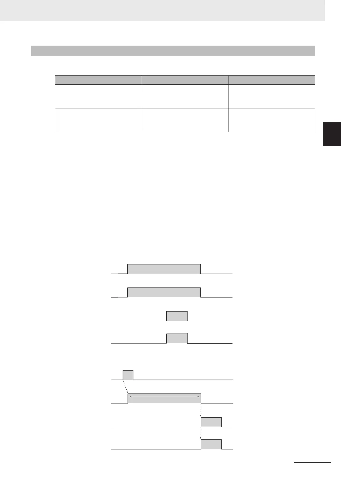
<Timing Chart (External Level)>
1. Trigger input
(TRIG signal)
2.
Output1
In Read Cycle
3.
Output2
Match
(or Good Read)
4.
Output3
Mismatch
(or No Read)
OFF
ON
OFF
ON
OFF
ON
Turns ON on Good Read.
OFF
ON
Read is executed only
while Trigger Input is ON.
Read is executed only
while Trigger Input is ON.
Turns ON when No Read.
<Timing Chart (External Edge)>
1. Trigger input
(TRIG signal)
2.
Output1
In Read Cycle
3.
Output2
Match
(or Good Read)
4.
Output3
Mismatch
(or No Read)
OFF
ON
OFF
ON
OFF
ON
In Read Cycle
Turns ON on Good Read.
Read executed by Trigger Input.
OFF
ON
Turns ON when No Read.
2 Controlling Operation and Data Output with Parallel
2 - 7
V430-F Series Autofocus Multicode Reader User Manual for Communication Settings
2-1 Controlling Operation and Data Output
with Parallel
2
2-1-5 Timing Charts for each Trigger Mode

 Loading...

