3-1-5
Tag Data Link Setting Methods
This section describes how to set data links for EtherNet/IP.
The communications areas in the PLC for which data links to the code reader are created are speci-
fied as tags and tag sets, and the connections are set for tag data link communications.
Precautions for Correct Use
When connecting to an NJ-series or CJ-series CPU Unit, install the EDS file that defines the
connection information for the code reader in to Sysmac Studio.
Download the EDS file from OMRON's website.
Tags, Tag Sets, and Connection Settings
The code reader has 6 types of Input Assemblies and 2 types of Output Assemblies, and one type can
be selected for each. The Data Structure changes based on the selected Assembly.
For more detailed information about Memory Allocation and the Data Structure of each Assembly
,
please refer to A-2 EtherNet/IP Detailed Specifications on page A - 3
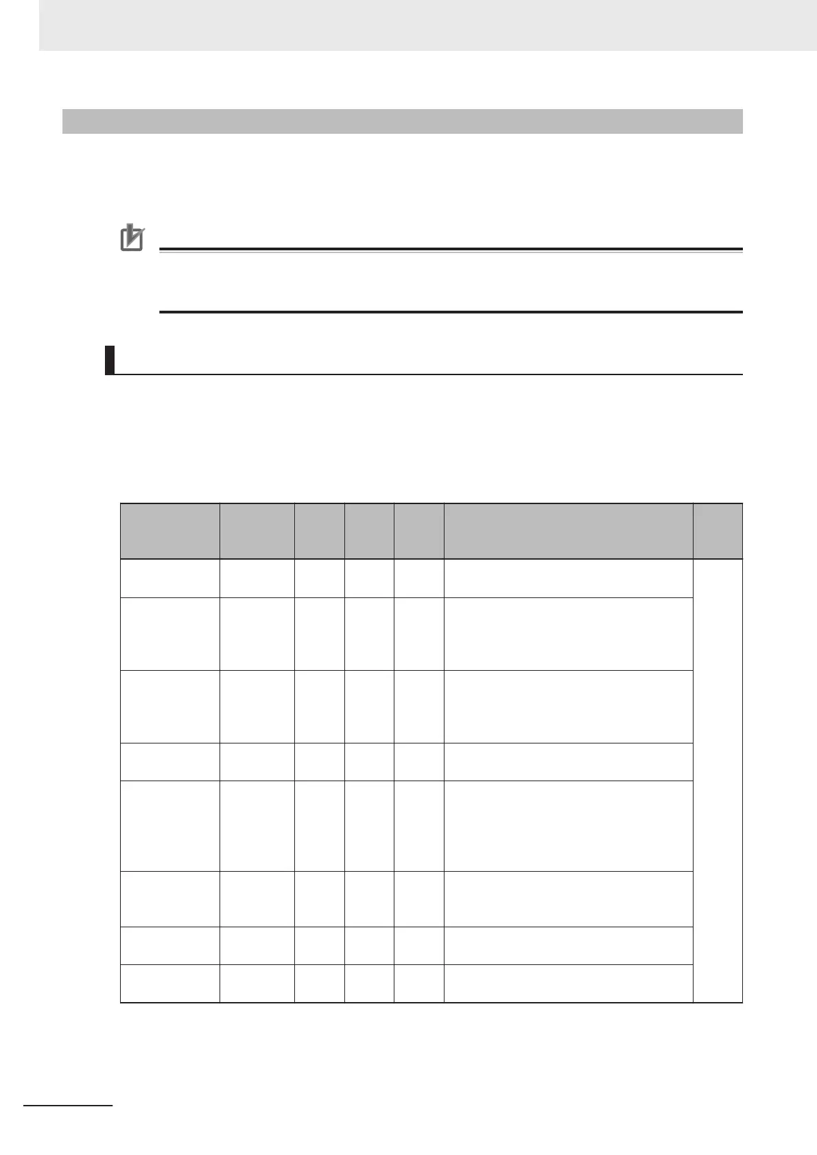
Assemblies
Assembly
Name
Connec-
tion I/O
Type
Input /
Out-
put
T
arget
Varia-
ble
Size
(bytes
)
Assembly Description
Data
Struc-
ture
Small Input As-
sembly
IO small Input 100 84 It is a compact, lightweight input assembly.
Holds 64 bytes of Read data.
*1
Big Input As-
sembly
IO big Input 101 176 Allows for more Device Status Information
to be stored for verification than what can
be stored with the Small Input Assembly
.
Holds 128 bytes of Read data.
MXL/SLC Input
Assembly
Input
MXLSLC
Input
102 258 Allows advanced Device Status Informa-
tion too large to be stored in Big Input As-
sembly to be stored for verification.
Holds 184 bytes of Read data.
1 Decode Input
Assembly
Input 1 De-
code
Input 103 500 Holds 436 bytes of Read data
4 Decode Input
Assembly
Input 4 De-
code
Input 104 500 Holds Read result information for 4 sym-
bols.
The first Read data is stored in a 160 byte
Area and the 2nd to 4th Read data are
stored in the 72 byte Area.
N Decode Input
Assembly
Input N
Decode
Input 105 500 Holds Symbol information and Read result
information for any number of symbols.
Holds 456 bytes of Read data.
Output Assem-
bly
‐ Output 197 4 For commands to be sent to the code read-
er
.
Output Assem-
bly (Legacy)
‐ Output
198 12 Commands and Command Echo for fixed
data can be sent to the code reader.
*1. A-2 EtherNet/IP Detailed Specifications on page A - 3refer to
3 Controlling Operation and Data Output with Ethernet
3 - 8
V430-F Series Autofocus Multicode Reader User Manual for Communication Settings

 Loading...

