3-1-8
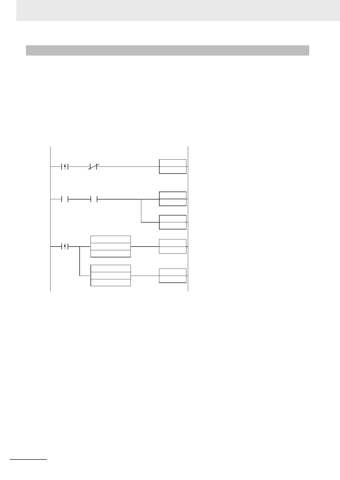
Sample Ladder Program
A sample ladder program to execute the following operation.
•
Input the Trigger Signal to execute T
riggered Read.
• The read character string (Decode Data) is compared with the Verification string (Master Symbol)
stored in the PLC.
• If they match, it is added to the OK/Match count, and if they do not match, it is added to the Mis-
match/NG count.
The following Input and Output Assemblies are used.
• Input Assembly: MXL/SLC Input Assembly (102)
• Output Assembly: Output Assembly (197)
SET
Trigger
W0.00
Single read
command bit
Decoding
Trigger
Trigger
RSET
W0.00
++L
OK Count
++L
NG Count
Data is Ready
RSET
Trigger
Acknowledge
=
Master Symbol
Decode Data
<>
Master Symbol
Decode Data
(1) When the flag for Triggered is ON, The Trigger Bit turns ON.
(2) The Trigger Acknowledged Bit (for detecting trigger input) is ON.
(3) When the Trigger Acknowledged Bit ON is detected, the Trigger Bit turns OFF.
(4) When Read is completed, the Data is Ready Bit turns ON.
(5) The Read string (Decode Data) is compared with the Verification string (Master Symbol).
(6) If the two strings match, the Match/OK Count is incremented by 1.
(7) If the two strings do not match, the Mismatch/NG Count is incremented by 1.
3 Controlling Operation and Data Output with Ethernet
3 - 14
V430-F Series Autofocus Multicode Reader User Manual for Communication Settings

 Loading...

