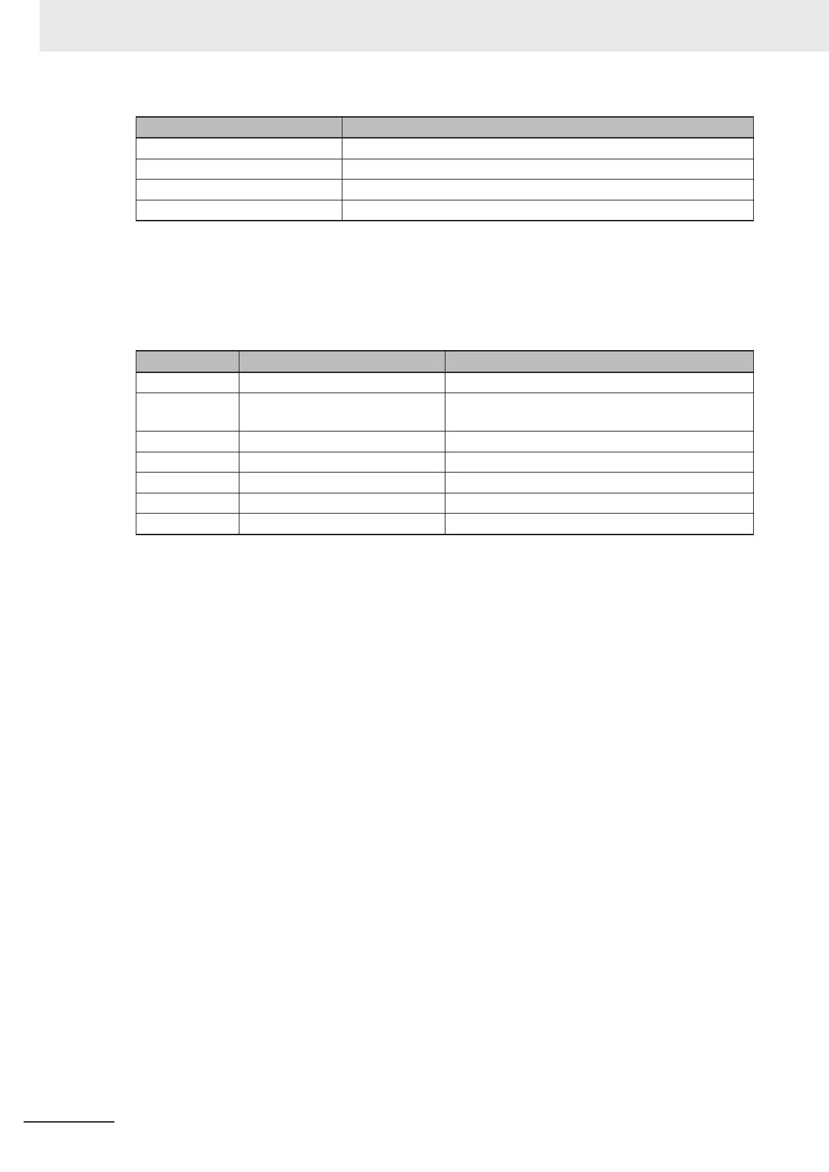
Bit Signal Name
0 OUTPUT 1
1 OUTPUT 2
2 OUTPUT 3
3 - 31 Reserved
Numeric value in Bit
0 = OFF
1 = ON
• Device Status
Displays code reader status
Bit State Description
0 Reserved ‐
1 New Master Requested When the bit is ON, the next read result is registered
as the Master Symbol.
2 - 7 Reserved ‐
8 Scanning Disabled When the bit is ON, the Read Cycle is Disabled.
9 - 15 Reserved ‐
16 In Read Cycle Bit is ON when In Read Cycle.
17 Actively Scanning When the bit is ON, the Read Cycle is Disabled.
• Read Cycle Sequence Counter
Stores the current Read Cycle Count.
• Trigger Counter
Stores the current total number of triggers input.
• Decode/Matchcode Counter
Stores one of the following.
(1) Total number of Good Reads (When Matchcode: Disabled)
(2) Total number of matches to the Master Symbol (When Matchcode: Enabled)
• Mismatch Counter
Stores the total number of Mismatches (not matching Master Symbol).
• No Read Counter
Stores the total number of No Reads.
• Decode Data Length
Stores the number of characters in the Read string.
• Decode Data String
Stores the Read string. When additional information such as Print Quality Grading Standard is set, it
is stored following the Read string.
Appendices
A - 6
V430-F Series Autofocus Multicode Reader User Manual for Communication Settings

 Loading...

