Section 5 EtherNet/IP Communications Protocol
Memory Assignments
This section describes the memory assignments for the Command Area and Response Area in the
PLC.
Memory is aligned in 16-bit units. The bit order for each field is little endian.
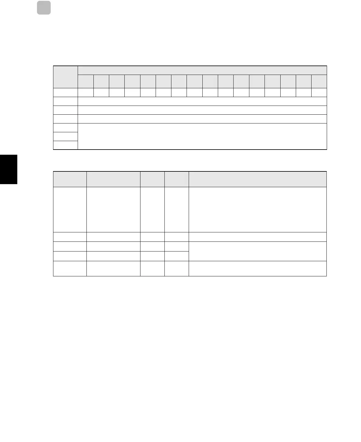
Command Area (from PLC Originator to Reader/Writer Target)
* Reserved (resv) bits are for future expansion. Do not turn them ON and OFF.
I/O
memory
offset
Bit
15 14 13 12 11 10 9 8 7 6 5 4 3 2 1 0
+0 Resv Resv Resv Resv Resv Resv Resv Resv Resv Resv Resv Resv Resv Resv Resv EXE
+1 Command Code
+2 Command Parameter 1
+3 Command Parameter 2
+4
Command Data (The format depends on the command.):
+N
Signal/data Name
Data
type
Size Description
EXE Command Execution
Request
BOOL 1 bit
• Turn ON this bit to send a request to the Reader/Writer to
execute a command. Set the command code and parameters
before you turn ON this bit.
• You can turn OFF this bit during execution of a
communications command with RF Tags to cancel
communications processing by the Reader/Writer.
CmdCode Command Code
WORD 2 bytes
This word stores the command code.
CmdParam1 Command Parameter 1
WORD 2 bytes
These words store the command parameters.
Refer to the sections for individual commands for details.
CmdParam2 Command Parameter 2
WORD 2 bytes
CmdData Command Data
--
These words store the command data.
Refer to the sections for individual commands for details.
 Loading...


