Section 3 Connections and Wiring
Connections and Wiring
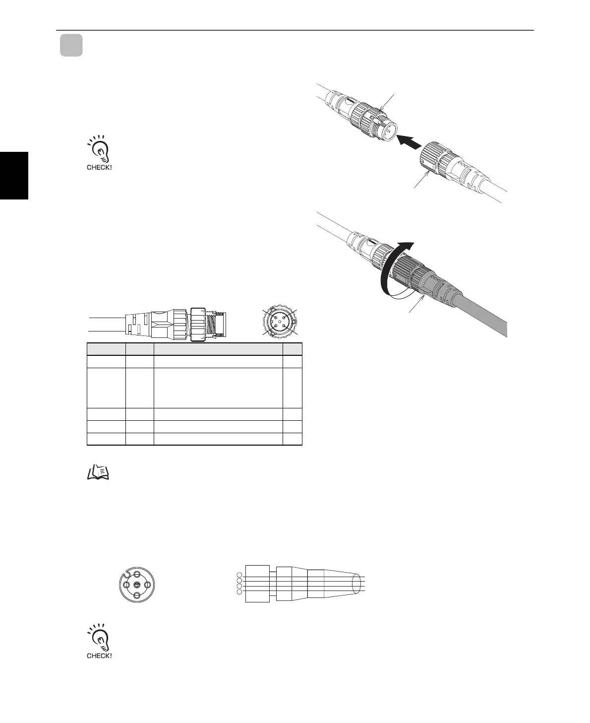
Connecting and Removing the Reader/Writer Power Cable and Ethernet Cable
Connecting Method
1. Hold onto the connector on the Power Cable and
insert it into the power connector on the Reader/
Writer.
Do not apply more than 30 N of force to the
connector on the Reader/Writer.
2. Turn the connector on the Power Cable clockwise
to lock it in place.
Recommended tightening torque: 0.39 to 0.49 N·m
Contact arrangement of the Reader/
Writer’s power connector
Refer to Functions in Section 2 Names and Functions of Components for information on the RUN mode, and Safe mode.
p.32
Contact arrangement and wiring diagram of the recommended cable (Model
XS5F-D42-80-F)
Read and understand the power cable manual before attempting to connect the power cable.
Pin No. Name Description I/O
124P+24 V ---
2CONT
Control signal (operating mode signal)
* Run Mode: Connect to +24 V and then start
the Reader/Writer.
Safe Mode: Connect to 0 V and then start
the Reader/Writer.
IN
324N0 V ---
4-- ---
Pin No. Name Description I/O
Reader/Writer power
supply connector
(M12 A-Coding, male)
Power supply connector on cable
Power supply connector on cable
1
2
3
4
Blue
Black
Brown
White
PinNo.
wirecolor
Wiringcable(Four-coretype)Contactarrangement
2
1
4
3
 Loading...


