Section 1 Application Flowchart
Application Flowchart
A simple application flowchart is described below. For correct application methods and details, refer to the
reference page or section given for each step.
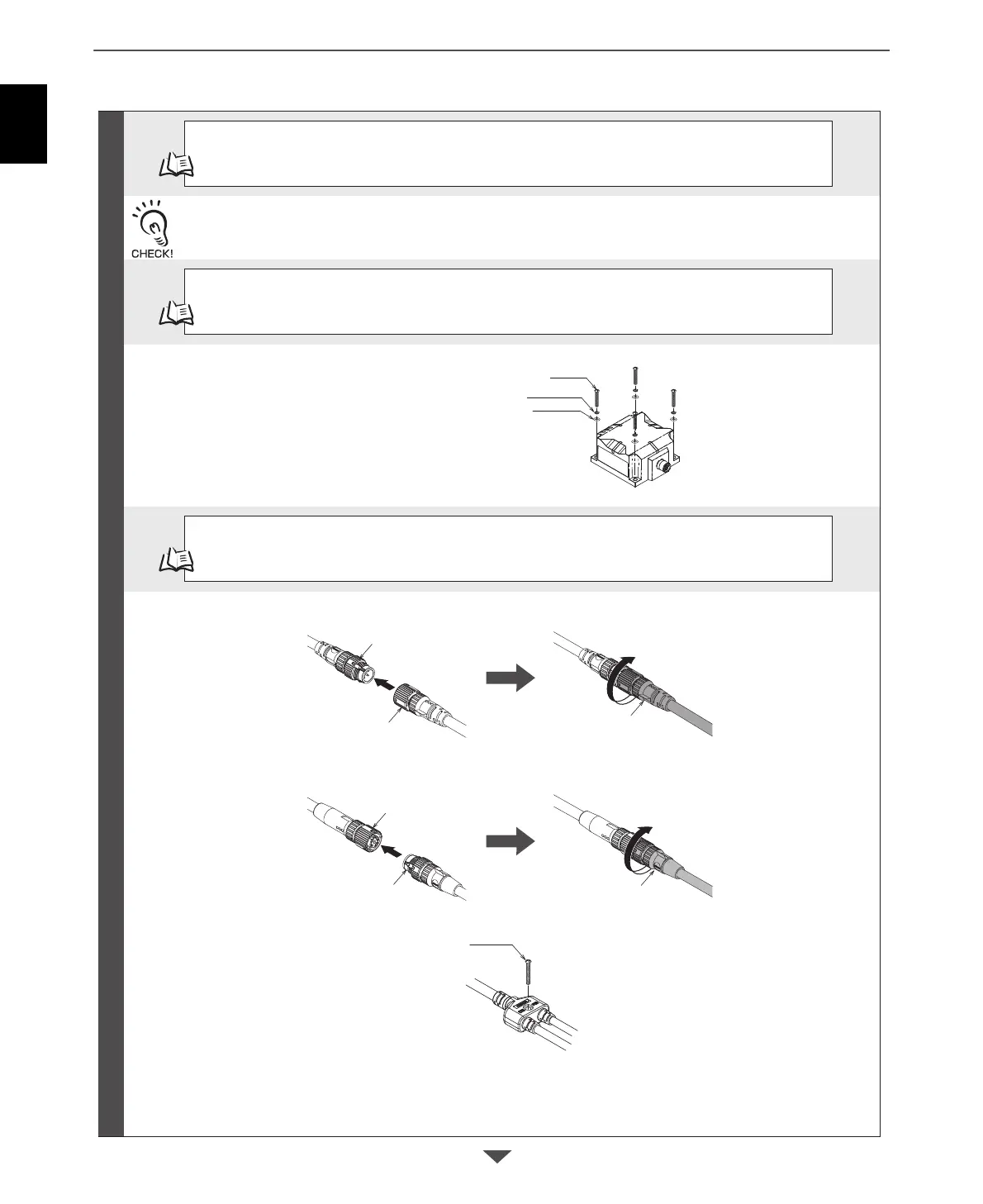
Spring washer
Flat washer
M4 screw
Reader/Writer power supply connector
(M12 A-Coding, male)
Power supply connector on cable
Power supply connector on cable
Ethernet connector on Reader/Writer
(M12 D-Coding, female)
Ethernet connector on cable
Ethernet connector on cable
M4 screw
p.232
Checking the Installation Environment
Refer to Reader/Writer Installation Precautions in Section 8 Appendices to confirm the conditions under which
the RFID System will not be influenced by surrounding metal on the Reader/Writer or mutual interference
between Reader/Writers.
p.80
Installation
Install the Reader/Writer with four M4 screws.
V680S-HMD63-EIP: Use two screws.
V680S-HMD64-EIP/-HMD66-EIP: Use four screws.
p.92
Connections and Wiring
Connect the Power Cable to a 24-VDC power supply.
Connect the Ethernet Cable to the host device (PLC) or Switching Hub.
Preparations
Insert the Power Cable into the power supply connector on the Reader/Writer (M12 A-Coding, female) and turn
the cable connector on the Reader/Writer end clockwise to lock it in place.
Mount the Branch Cable with one M4 screw.
Recommended tightening torque: 0.39 to 0.49 N·m
Insert the Ethernet Cable into the Ethernet connector on the Reader/Writer (M12 D-Coding, male) and turn the
cable connector on the Reader/Writer end clockwise to lock it in place.
 Loading...


