Section 2 Component Names
Connector
Power Supply Connector (M12 A-Coding)
Ethernet Connector (M12 D-Coding)
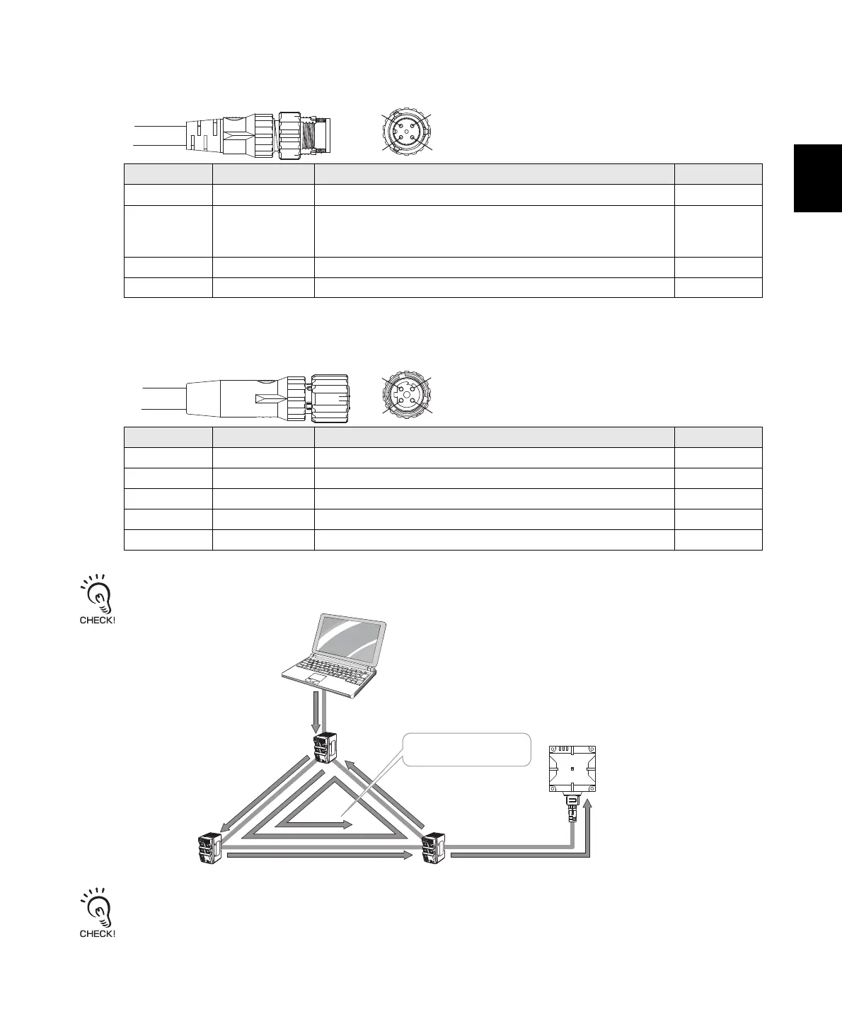
If an Ethernet network is configured into a loop as shown below, broadcast packets are accumulated in the band, and the
communication is disabled. Therefore, do not configure the Ethernet network into a loop.
When a large amount of broadcast packets or multicast packets flow into the Ethernet network, Reader/Writers may stop its
operation. Please do not send a large amount of packet. Please separate the Reader/Writers from the network segment that
broadcast or multicast packets flow.
Pin No. Name Description I/O
1 24P +24 V ---
2CONT
Control signal (operating mode signal)
* Run Mode: Connect to +24 V and then start the Reader/Writer.
Safe Mode: Connect to 0 V and then start the Reader/Writer.
IN
324N0 V ---
4-- ---
Pin No. Name Description I/O
1 TD+ Ethernet send signal + OUT
2 RD+ Ethernet receive signal + IN
3 TD- Ethernet send signal - OUT
4 RD- Ethernet receive signal - IN
Housing FG Frame ground ---
Power Supply Connector (M12 A-Coding, male)
1
2
4
3
Ethernet Connector (M12 D-Coding, female)
2
1
3
4
Sending broadcast storm
Reader/Writer
HUB
HUB
HUB
Broadcast storm
Communication disabled
 Loading...


