13
En
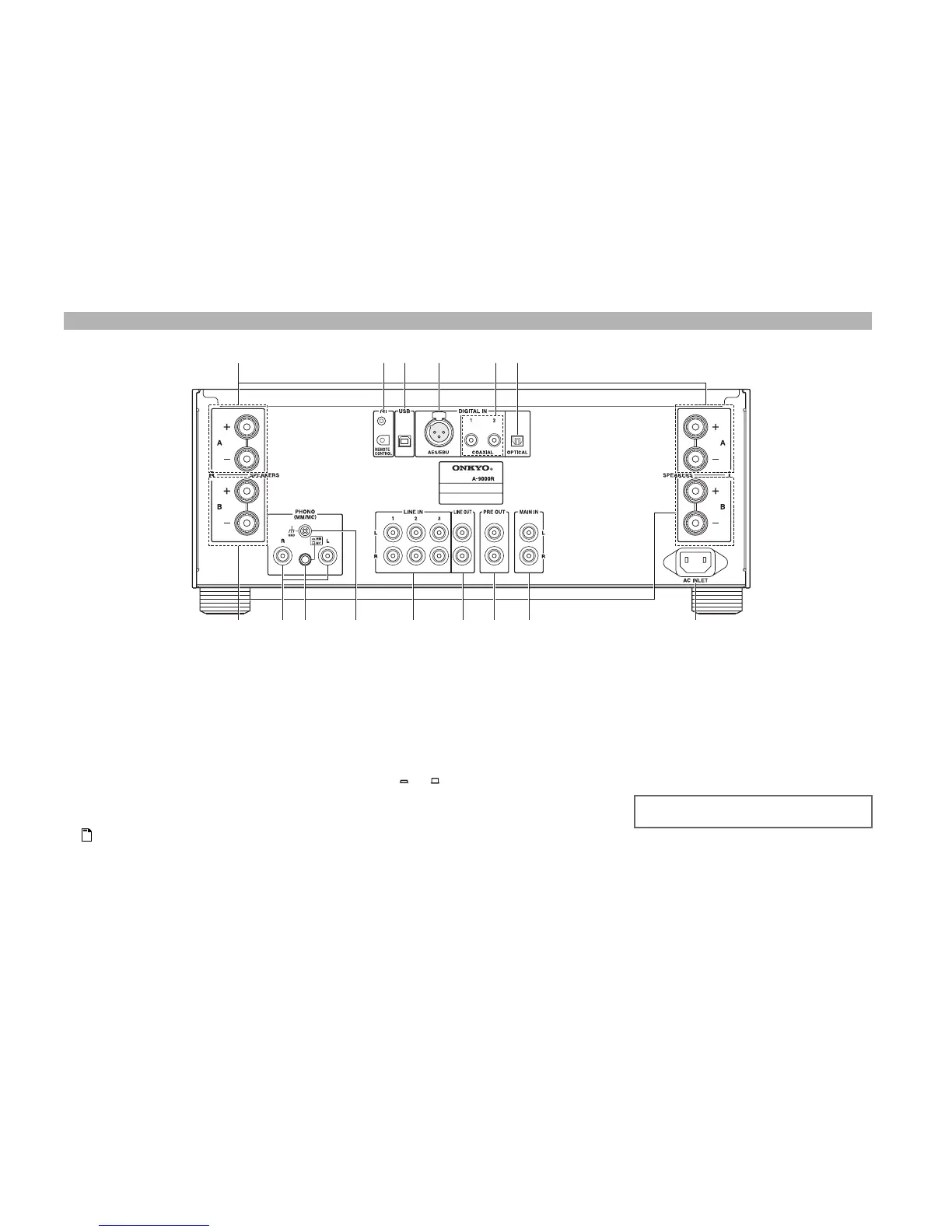
a SPEAKERS A terminals
Connect Speakers A.
b u REMOTE CONTROL jacks
Connect Onkyo components such as Onkyo Docks,
CD Players, or Network Tuner with u (Remote
Interactive) jacks.
c USB port
Connects a PC. The music files of your PC are played
through the integrated amplifier.
d DIGITAL IN AES/EBU jack
Connects components such as CD players with
balanced AES/EBU output.
Note
• Be careful not to connect components with analog
XLR output.
e DIGITAL IN COAXIAL 1/2 jacks
Connect components such as CD players with coaxial
digital audio output.
f DIGITAL IN OPTICAL jack
Connects components such as CD players with optical
digital audio output.
g SPEAKERS B terminals
Connect Speakers B.
h PHONO (MM/MC) L/R jacks
Connect a turntable with analog audio output.
i MM/MC selector
Set this selector according to the turntable’s cartridge
format ( MM/ MC).
j GND screw
Connects the turntable’s ground wire.
k LINE IN 1/2/3 L/R jacks
Connect playback devices with analog audio output.
l LINE OUT L/R jacks
Connect components such as analog line-level
sources. The input signals are output with no level
adjustment.
m PRE OUT L/R jacks
Connect a power amplifier when the integrated
amplifier is used as a preamplifier (Pre mode).
n MAIN IN L/R jacks
Connect a preamplifier when the integrated amplifier
is used as a power amplifier (Main mode).
o AC INLET
Connects the supplied power cord. The other end of
the power cord should be connected to a suitable wall
outlet.
Rear Panel
a b
e
d
c f
gh j k lmnoi
See “Connections” for connection information
(➔ pages 15 to 27).
 Loading...