-16-
[4] Connect wires to the terminals. Refer to page 5
Connect the power cable to the power supply terminals, and relay output cables to the output terminals.
When linking to other devices, connect the other device to the input terminals.
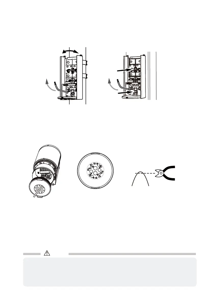
Cut the terminal cover with scissors and make a hole according to the wire diameter. (Select the smallest
from among similar sizes.)
Wiring size
︓
Φ2 to 6mm
(3/32 to 1/4in.)
[3] When running a wire from a pole, cut the terminal cover with nippers by referring to the wiring holes on
page 14, and put wires through the sensor housing.
Do not use a powered screwdriver when mounting the unit to a pole.
● Round Pole
Adjust the position so that the front of the base
faces the desired angle, and mount it to the pole.
Screw
Screw
● Square Pole
When pilot holes of ø4.3mm (0.17in.) have been made,
use M4 screws (included) and nuts (not included) for
mounting.
Caution
• Do not pull the cable. It may cause the terminal cover to come off and allow water to leak in.
• If a hole with wrong diameter is made
Apply silicon adhesive and fill the hole. When doing so, be careful not to overfill the adhesive over the
hole.
If the hole is not filled, water may leak in and it may result in breakage.
Only cut the tip using nippers.
This will avoid making a hole too big.