-17-
[8] Attach the top and bottom covers.
[9] Tighten the screws on the top and bottom covers.
* If a screw is lost, use an M3 × 6 Philips screw.
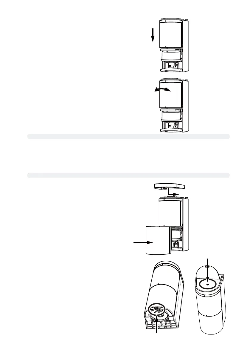
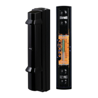
[5] Install the sensor unit into the sensor housing.
At this point, push excess wire out on the pole side.
[6] Rotate the sensor unit to adjust its angle to meet the sensor
installation condition (adjustable angle: 96° to left and right).
[7]
Verify the detection area according to “6-1.Applicatiions” “6-2.Concept of Detection Range” (P.8)
[8] Perform calibration according to “7-3. Calibration” (P.18)
[9] Verify the system operation according to "7-4. Detection area check" (P.19).
[10] If necessary, set various parameters referring to page 24 and more
Log in to the sensor with smartphone App
Log out from the sensor with smartphone App