Chapter-2
Before Using
Operation Mode and Control Panel Description
2.7
Normally, the scanner is operated by serial communication control, but simple operation setting by the
control panel is also available.
Operation Mode 2.7.1
Following are use as reading trigger in a readable state like operation.
・Command trigger by serial communication (USB-COM/RS-232C)
・External trigger signal (RS-232C)
・Auto trigger
・Trigger key
Used when testing the read rate.
The read rate is displayed on the indicator LED every 10 times.
When reading distance and the code to read is fixed, reading will
stabilized by setting the optimum exposure.
When the tuning is successes, code limited and exposures setting etc.
are registered to the current bank. Also, the reading rate is displayed on
the LED indicator.
Area to register the exposure etc. adjusted in the tuning mode. 1-7 can
be register to the bank, default is 1.
Aiming lights and if code can be read, displays whether the code is close
to the center coordinate of the image sensor to LED indicator.
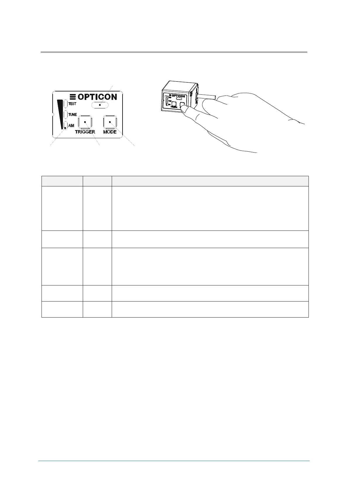
Buzzer Holes
Mode Key
Trigger Key
Status LED
Control Panel