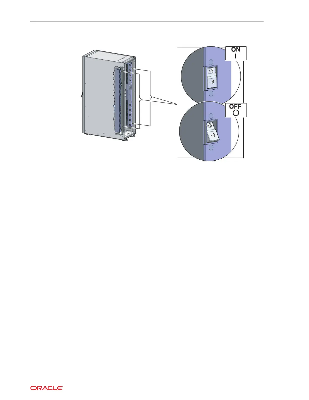
Figure 4-9 PDU Switch Locations
2. Verify the expected power LEDs are on. The LEDs are located as follows:
• Database servers: Right-hand LED
• Exadata Storage Servers: Top LED
• Cisco switch: Left LED (viewed from front) is green, and the other LEDs are
red
• InfiniBand switches: Left LED (viewed from front) labeled PS0, or right LED
(viewed from front) labeled PS1
• KVM switch on Oracle Exadata Database Machine X2-2: Lower LED B
• KMM switch on Oracle Exadata Database Machine X2-2: Only supplied by
PDU B
3. Connect power to PDU A. Ensure the breaker switches are in the OFF position
before connecting the power cables.
4. Switch on the PDU A circuit breakers, one at a time.
5. Verify the expected LEDs are on.
6. Perform a visual check of all cable connections in the rack. Do not press every
connector to verify connection.
7. Verify the OK LED is blinking standby for all systems. The OK LED blinks on for
0.1 seconds, once every 3 seconds when in standby mode. The OK LED does not
blink when the ILOM is starting. The LED remains dark until it goes to standby
mode after 2 to 3 minutes.
Related Topics:
• Reviewing Safety Guidelines (page 4-1)
Chapter 4
Powering on the System the First Time
4-14