Overview of ZS5-4 Controller
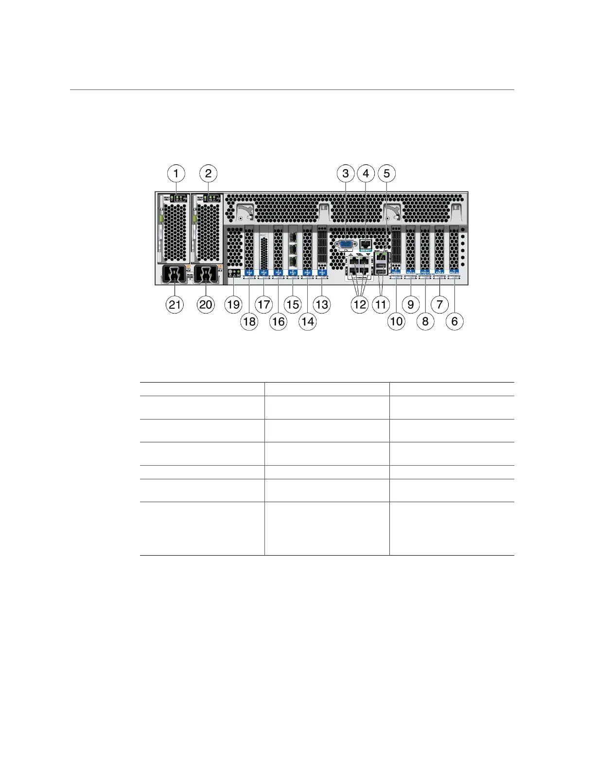
FIGURE 23
ZS5-4 Rear Panel
1 Power Supply Unit (PSU) 0 2 PSU 1 3 DB-15 VGA port
4 SER MGT port 5 Service Processor (SP) NET MGT
port
6 First PCle (slot 11)
7 Fifth PCIe (slot 10) 8 Third 4x4 SAS HBA or seventh
PCIe (slot 9)
9 Second PCIe (slot 8)
10 4X4 SAS HBA (slot 7) 11 Two USB 2.0 ports 12 Network (NET) 10 Gb Ethernet
ports, NET 0 - NET 3
13 4X4 SAS HBA (slot 6) 14 Third PCIe (slot 5) 15 Cluster interface card (slot 4)
16 Fourth 4X4 SAS HBA or sixth
PCIe (slot 3)
17 Internal SAS-3 HBA (slot 2) 18 Fourth PCIe (slot 1)
19 System status LEDs (left to right)
■ Power/OK (green)
■ Attention (amber)
■ Locate (white)
20 PSU 1 AC inlet 21 PSU 0 AC inlet
Cluster Interface Card Compatibility - The ZS5-4 controller contains a Version 3 cluster
interface card, which is incompatible with Version 2.
For information about how to connect cables to form a cluster, see “Connecting Cluster Cables”
in Oracle ZFS Storage Appliance Cabling Guide.
Installation Prerequisites and Hardware Overviews 41

 Loading...


