Overview of ZS5-2 Controller
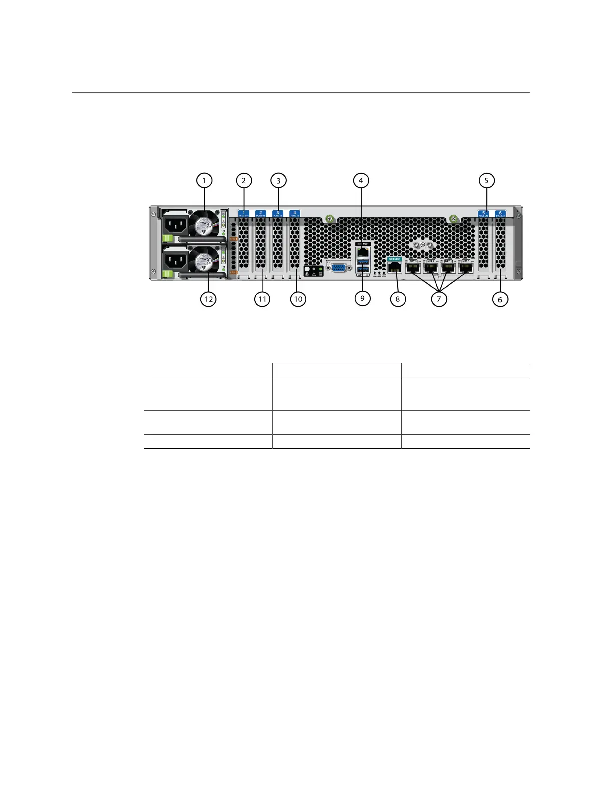
FIGURE 25
ZS5-2 Rear Panel
1 Power Supply Unit (PSU) 1 2 Second PCle option (slot 1) 3 Third PCle option (slot 3)
4 Network Management (NET
MGT) 10/100/1000 BASE-T
Ethernet port
5 First PCle option (slot 5) 6 Second 4x4 SAS HBA, or fourth
PCle option (slot 6)
7 Network (NET) 10 GbE ports:
NET 0, NET 1, NET 2, NET 3
8 SER MGT port 9 Two USB 3.0 ports
10 Cluster interface card (slot 4) 11 First 4x4 SAS HBA (slot 2) 12 Power Supply Unit (PSU) 0
Cluster Interface Card Compatibility - The ZS5-2 controller contains a Version 3 cluster
interface card, which is incompatible with Version 2.
For information about how to connect cables to form a cluster, see “Connecting Cluster Cables”
in Oracle ZFS Storage Appliance Cabling Guide.
Cable Management Arm
The following figure identifies the components of the cable management arm (CMA). For
installation instructions, see “Installing a ZS5-2 Cable Management Arm” on page 116.
Installation Prerequisites and Hardware Overviews 45

 Loading...


