Overview of 7420 Controller
7420 Front Panel Components
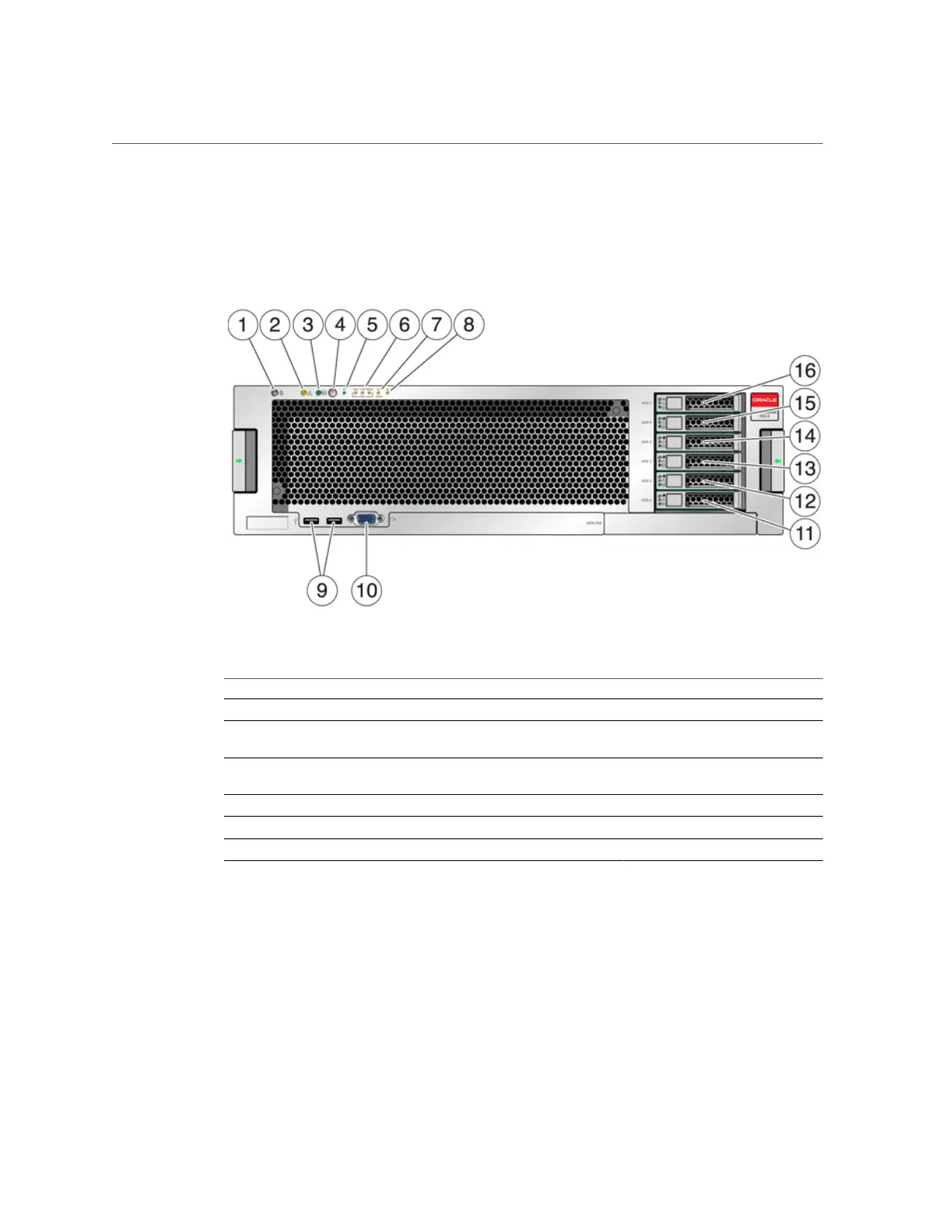
FIGURE 36
7420 Front Panel
Figure Legend
1 Locator LED and button (white) 2 Service Required LED (amber) 3 Power/OK LED (green)
4 Power button 5 Service Processor (SP) OK LED
(green)
6 Fan/CPU/Memory Service
Required LED
7 Power Supply (PS) Service
Required LED
8 Over Temperature Warning LED 9 USB 2.0 Connectors
10 DB-15 video connector 11 Boot drive 0 (mirrored) 12 Boot drive 1 (mirrored)
13 SSD 2 (optional) 14 SSD 3 (optional) 15 SSD 4 (optional)
16 SSD 5 (optional)
The 7420 M2 has two SAS-2 system boot drives in slots 0 and 1, configured as a mirrored pair.
Up to four SAS-2 read cache SSDs may fill slots 2 through 5, in order. In a 7420 M2 cluster, the
number of SSDs installed in each controller can vary.
7420 controllers have two SATA system boot drives in slots 0 and 1, configured as a mirrored
pair. Zero, two, three, or four read cache SSDs, may optionally fill slots 2 through 5, in order. In
a 7420 cluster, the number of SSDs installed in both controllers must match.
Installation Prerequisites and Hardware Overviews 63

 Loading...


