OPTIMOD-FM OPERATION
4-3
Removing and Replacing Parts and Assemblies
[See Section 6 of this manual for PC board and parts locator diagrams.]
6. Removing the Top Cover.
To access the main board, power supply board or display assembly, you must remove the
top cover.
A) Disconnect the 8400 and remove it from the rack.
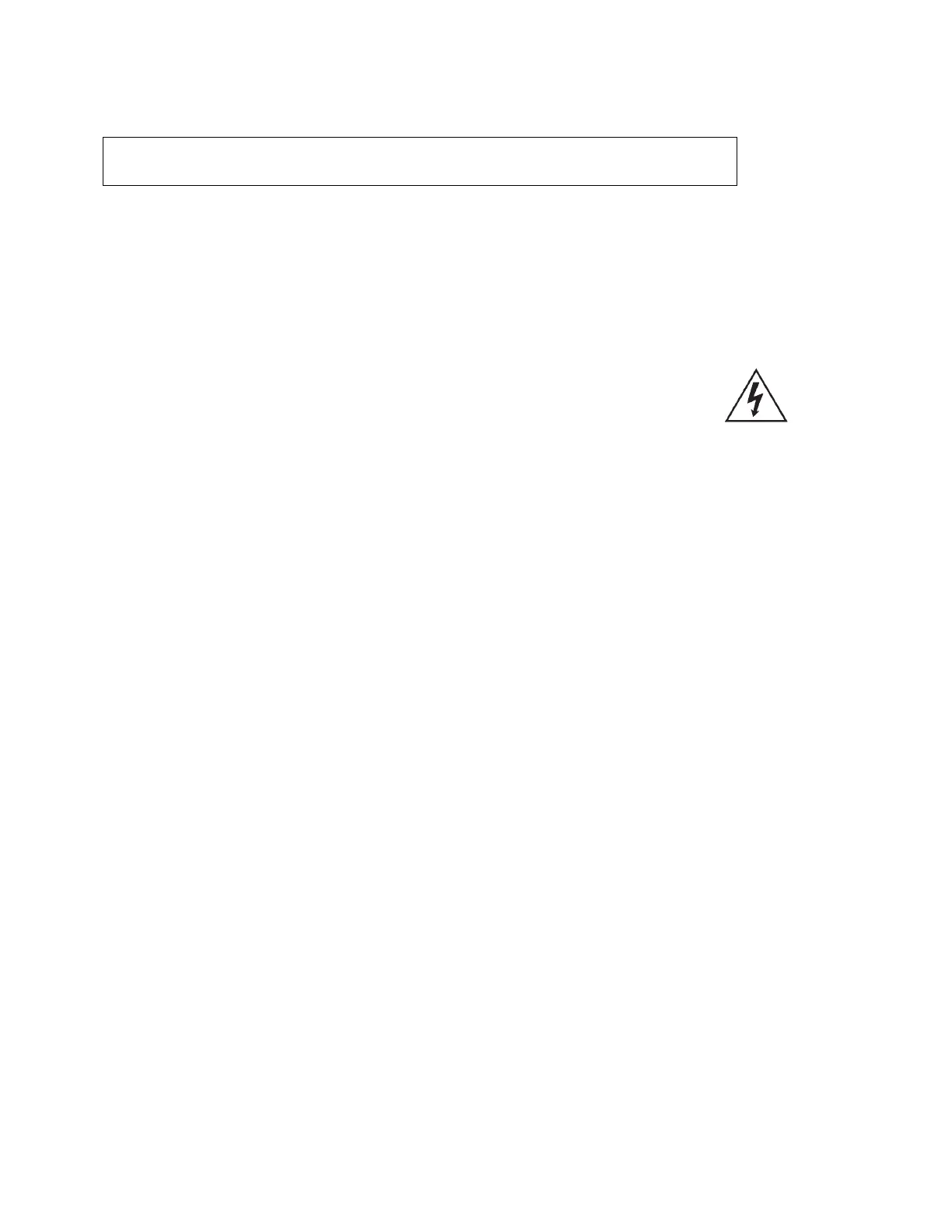
Be sure power is disconnected before removing the cover.
Hazardous voltage is exposed when the unit is open and the power is ON.
B) Set the unit upright on a padded surface with the front panel facing you.
C) Remove all eighteen screws holding the top cover in place and lift the top cover
off.
Use a #1 Phillips screwdriver.
7. Removing the Power Supply assembly and cleaning the fan.
The entire power supply is a plug-in assembly. To remove the power supply it is unnec-
essary to remove the 8400 from the rack or to remove the top cover.
A) Be sure that the AC line cord is disconnected from the power supply.
B) Remove the seven #1 Phillips screws holding the power supply assembly to the
rear of the chassis.
C) Using the handle on the back of the supply, pull it straight back. It will unplug from
its socket.
The fan is part of the power supply assembly. Cleaning or replacing the fan
only requires that the power supply be removed. As stated above, this can be
done without removing the 8400 from the rack.
8. Removing the Input/Output Assembly
The input/output assembly is a plug-in assembly. It can be removed with the 8400 still
mounted in a rack and with the 8400’s top cover in place.
A) Make sure that AC power is disconnected from the 8400.
B) Remove the six Phillips screws holding the input/output assembly to the rear panel.
C) Pull the assembly directly back to unplug it from the motherboard.
You can use the BNC connectors and the tabs on the female XLR connec-
tors to grasp the assembly.