OPTIMOD-FM TECHNICAL DATA
6-21
21318.510.01 CAPACITOR, TANTALUM, 1.0uF, 35V, B-CASE C1 C14 C15 C35 C48 C60 C78
C88
21321.633.01 CAPACITOR, 33uf, TANTALUM, 6032 D C26 C59
21322.547.01 CAPACITOR, 4.7uf, TANTALUM, 6032B C43 C51 C53
22016.000.01 DIODE, MMSZ5231B, SOD-123 D11
22083.015.01 DIODE, SURGE SUPPRESSOR, 15 VOLT D10
22101.001.01 DIODE, 1N4148WT/R D1 D3 D6 D7 D8 D9
22209.000.01 DIODE, SHOT 1A, 60V, SMD D15 D16
23214.000.01 TRANSISTOR NPN MMBT3904 Q1 Q2
24326.000.01 IC, REGULATOR, 1086, 3.3 VOLT U8 U22
24327.000.01 IC, REGULATOR, 1086, 3.6 VOLT U19
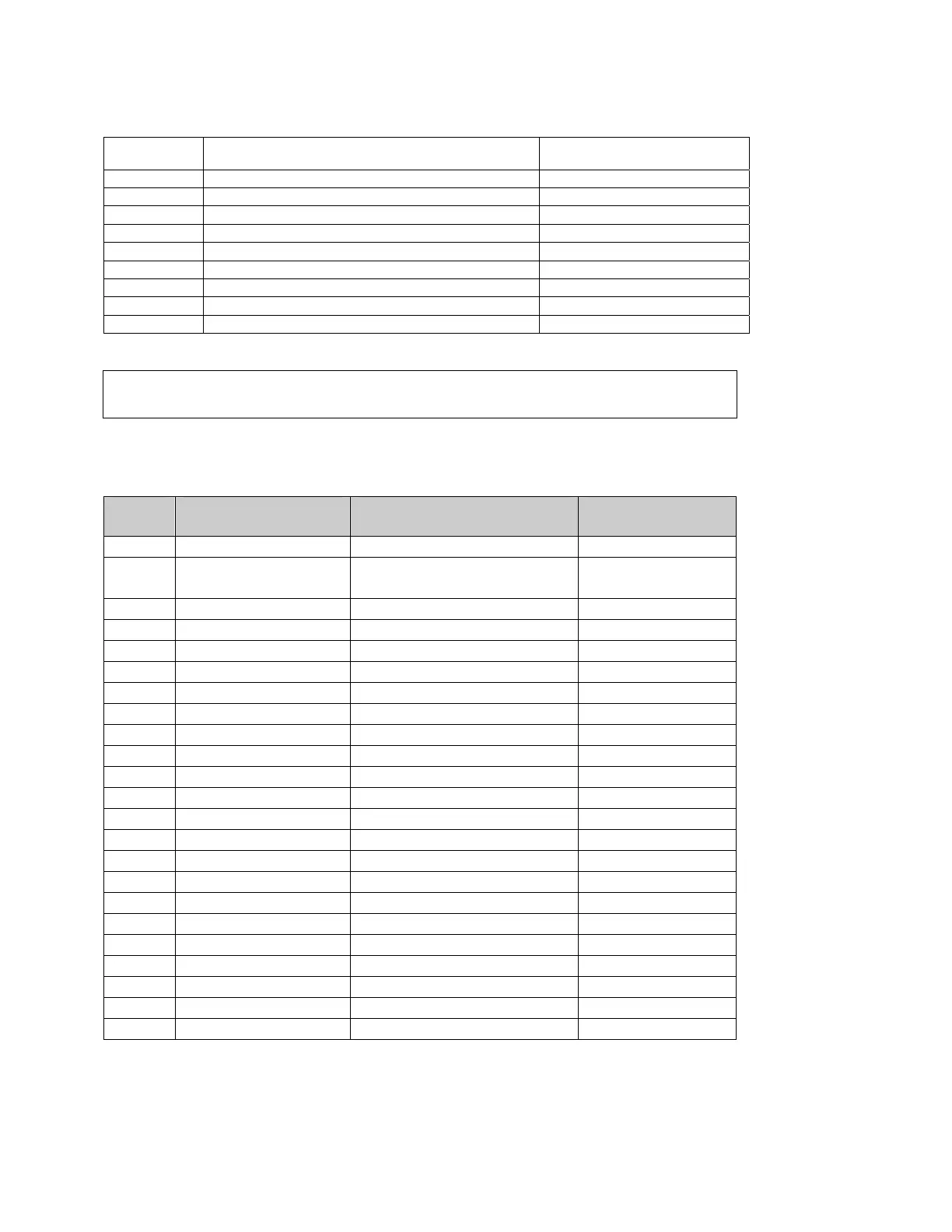
Schematics, Assembly Drawings
The following drawings are included in this manual. These are the sections of the 8400
likely to contain parts serviceable outside the Orban factory.
Page Function Description Drawing
6-22
Chassis Circuit Board Locator Top view
6-23
Backplane Interface
Board
Interconnects main circuit boards Schematic 1 of 1
6-24
Power supply Assembly Drawing
6-25
Schematic 1 of 1
6-26
CPU/Remote/RS232 Serial port 1 & 2 support Assembly Drawing
6-27
Schematic 1 of 1
6-28
Display Interface board containing: Assembly Drawing
6-29
Connectors and Headers Schematic 1 of 3
6-30
Color LCD support Schematic 2 of 3
6-31
Color LCD power supply Schematic 3 of 3
6-32
Rotary encoder board Assembly Drawing
6-33
Schematic 1 of 1
6-34
Headphone board Assembly Drawing
6-35
Schematic 1 of 1
6-36
Composite I/O Daughterboard with BNCs Assembly Drawing
6-37
Schematic 1 of 1
6-38
FM Input/Output Board containing: Assembly Drawing
6-39
Analog Input 1 of 5
6-40
Analog Output 2 of 5
6-41
Composite and SCA 3 of 5
6-42
Control and Digital I/O 4 of 5
6-43
Interface and Power Distribution 5 of 5
6-44
Block Diagram Shows signal processing