2-10
INSTALLATION ORBAN Model 8400
eases thermal stresses on the output amplifier in the stereo encoder, and can
thus extend equipment life.
If the Orban CIT25 Composite Isolation Transformer is used, the exciter
must present a 1kΩ or greater load to the transformer for proper transformer
operation.
Designed to be installed adjacent to each exciter, the CIT25 Composite Iso-
lation Transformer provides ground loop isolation between the 8400 com-
posite output and the exciter’s input, and presents the 8400 with a balanced,
floating load.
Even when its composite limiter is being heavily used, the 8400 will always
protect the stereo pilot tone by at least 60 dB (±250Hz from 19 kHz) and
will protect the region from 55 kHz to 100 kHz by at least 75 dB (re 100%
modulation).
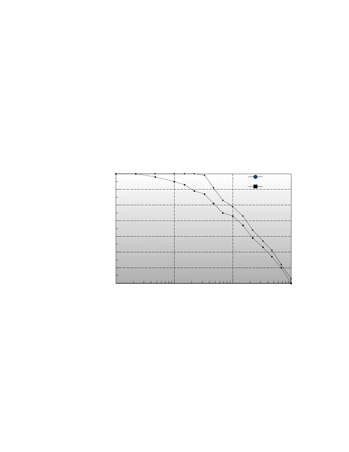
0.0001 0.001 0.01 0.1
Load Capacitance (μF)
15kHz Separation (dB)
60.0
55.0
50.0
45.0
40.0
35.0
30.0
25.0
Separation vs. Load Capacitance
for 8400 and 8200
Sep 8400
Sep 8200
Fig. 2-3: Separation vs. load capacitance for 8400 and Orban stereo encoders using
8200-style line driver (8200, 2200, 8208, and 8218). Test frequency = 15 kHz.
The subcarrier inputs are provided for convenience in summing subcarriers into the
baseband prior to their presentation to the FM exciter.
The subcarrier inputs will accept any subcarrier (or combinations of subcar-
riers) above 23 kHz. Below 20 kHz, sensitivity rolls off at 6 dB/octave to
suppress hum that might otherwise be introduced into the subcarrier inputs,
which are unbalanced.
The subcarrier inputs are mixed into the 8400’s composite output in the ana-
log domain, after D/A conversion of the 8400 stereo encoder’s output.