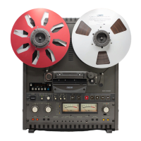
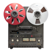
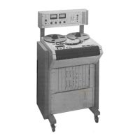
MX-5050 Operation and Maintenance Manual
May 1992
Section 3 Controls and Indicators
3 - 11
The numbers in bracket [ ] refer to Figures 3-7 and 3-8.
[1] LINE OUTPUT Connector
These XL type connectors are for audio output. See §2.2.2 for pin
assignment.
[2] LINE INPUT Connector
These XL type connectors are for audio input. See §2.2.2 for pin assignment.
[3] Microphone Input Connector
These XL type connectors are for microphone input.
[4] Microphone Attenuator Switch
When this switch is set to the –20dB position, this switch attenuates the
microphone input level by 20dB. If attenuation is not necessary, set this to
0dB. When this switch is set to the OFF position, the MIC input is not active.
[5] REF FLUX Switch
This switch selects the Reference Flux Level from L(185)/M (250)/H (320
nWb/m).
[6] Equalizer Switch
This switch changes the Equalizer setting to IEC or NAB.
[7] Output Level Switch
This switch selects the output level from +4dBu/-16dBu.
[8] GROUND Terminal
This is the auxiliary ground terminal. Connect equipment not connected to the
AC earth to this terminal.
[9] POWER Connector
This connector is for the supplied AC power cable.
[10] PARALLEL I/O Connector
This is the OTARI standard Parallel I/O connector. This 37 pin connector
includes ports for Transport Control Command Status Tally Signal and
External Capstan Speed Control Signal. For details refer to § 3.7.