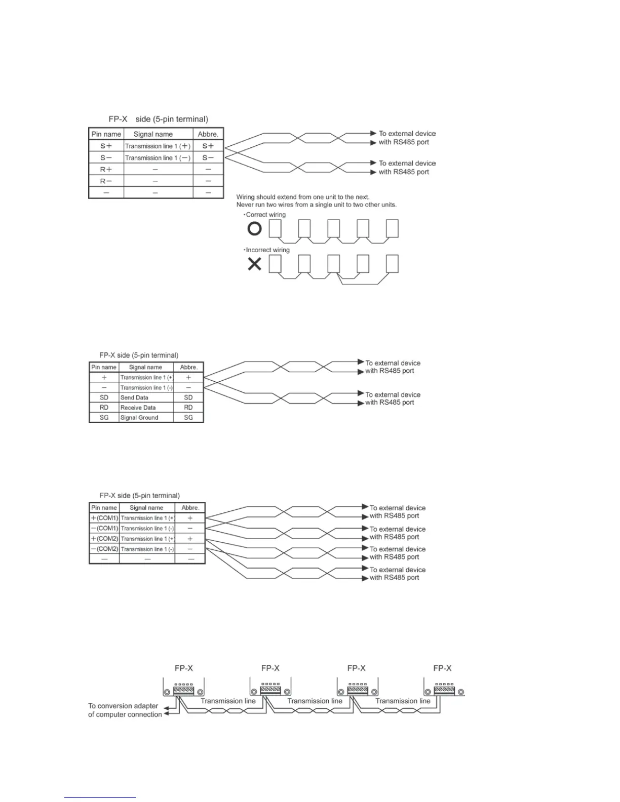
Connection with external devices
AFPX-COM3 (when setting RS485)
Connection diagram
With 1:N communication, the various RS485 devices are connected using twisted pair cables. Use only
one (+) and (-) terminals.
AFPX-COM4
Connection diagram
In case of using the AFPX-COM4, connect two cables each to the (+) terminal and (-) terminal.
Use the wires of the same cross-sectional area which should be 0.5 mm
2
.
AFPX-COM6
Connection diagram
In case of using the AFPX-COM6, connect two cables each to the (+) terminal and (-) terminal.
Use the wires of the same cross-sectional area which should be 0.5 mm
2
.
Note) Non-insulated between the COM1 and COM2.
Setting of terminal unit
The terminal unit is specified with the dip switch located in the communication cassette.
 Loading...