25
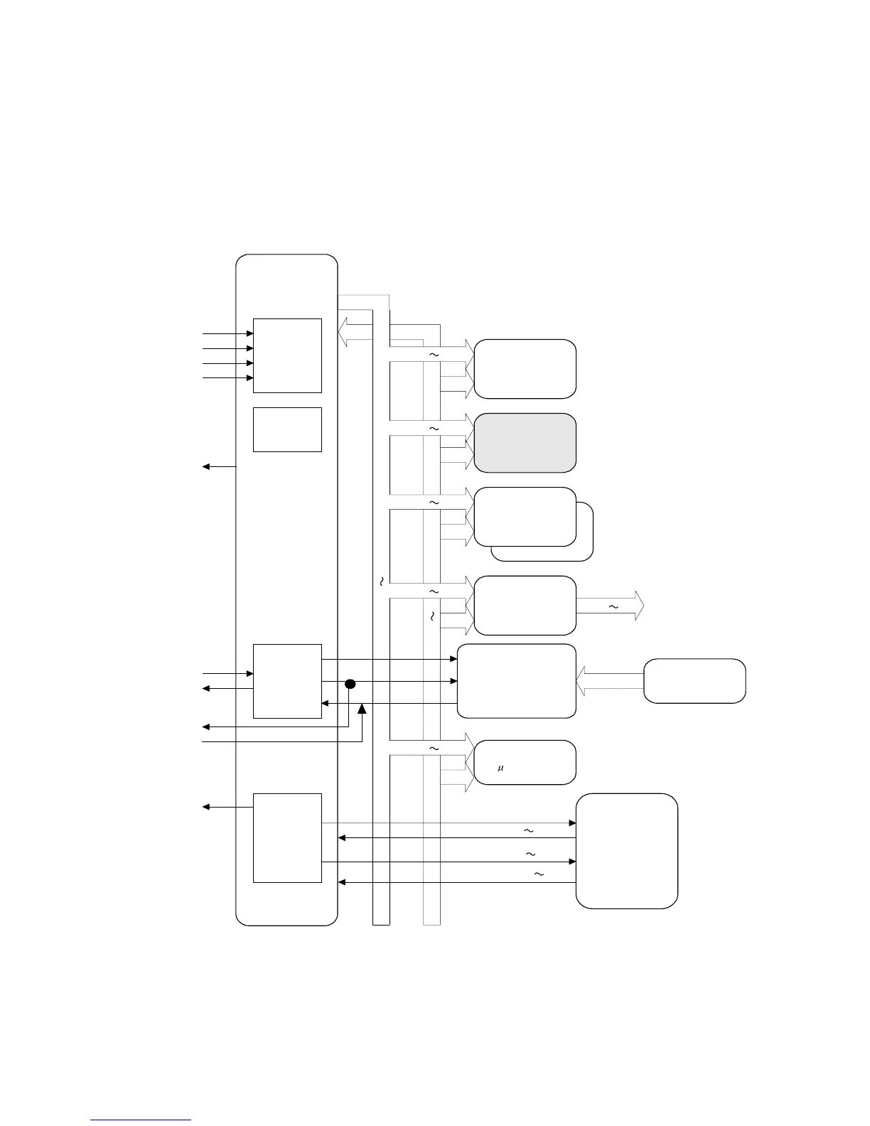
1.1.14. Panel PC Board
This Panel PC Board consists of Panel Control Sub-CPU, LCD Controller, Touch Panel Controller, S-RAM
Memory, FLASH Memory (Program, Image Data), Alarm IC (Backup), LED, and Key Switch.
The Sub-CPU receives the command of synchronized serial data from SC PCB and executes LCD Display,
LED Lamp, Switching Scan, Key Touch Sound, and Alarm Sound. The signal PON is turned to LOW with
the command from SC PCB and shifts to Sleep Mode. When Sleep Mode (Auto Off) is on, only +5VP is
reactivated and +5V (for LED Driver) and +24V (for Status LED, Alarm, and Back light) is cut off. After
detecting the signal nWAKEUP which is input from SC PCB, the signal nPOWSAVE is turned to HIGH in
order to recover from Sleep Mode and reactivate the main power of the machine.
)
)
A
A1
A1
A3 1
LCD Module
(Touch Panel
Controller)
(LCD Controller)
Touch Panel
CPU (SH7041)
nWAKEUP
NMI
nSLPKY
nRTCIRQ
POWSAVE
TXD
DBGTX
DBGRX
BZCLK
RXD
MTU
(5ch)
SCI
(2ch)
Matrix Data
A3 1
TPCRX
KEYIN0 7
SCN0 7
LED0 7
LEDCT0,1
TPCTX
TPCCLK
A15 1
D3 1
A15 1
A19 1
A21 1
D15 1
A21 1
PNL2
(SW Board)
KEY: MAX40
LED: MAX14
RTC
PD4992
EMU601A2MA12
EDMMR63B0F
ADS7843
TPC
LCDC
S-RAM (64KB)
F-ROM (Program)
(16Mx16)
INTC
(8ch+NMI)
A/D
F-ROM (Program)
(8M/16Mx16)
M66272FP