1 Applicable signals 4
2 Safety Precautions
5
2.1. General Guidelines
5
3 Prevention of Electro Static Discharge (ESD) to
Electrostatically Sensitive (ES) Devices
6
4 About lead free solder (PbF)
7
5 Service Hint
8
6 Disassembly
9
6.1. Removal of the Back Cover
9
6.2. Removal of the HA-Board
9
6.3. Removal of the HDD-Board
9
6.4. Removal of the DS-Board
9
6.5. Removal of the HX-Board
10
6.6. Removal of the PB-Board
10
6.7. Removal of the DN-Board
10
6.8. Removal of the D-Board
10
6.9. Removal of the P-Board
11
6.10. Removal of the SU-Board and the SD-Board
11
6.11. Removal of the SC-Board
12
6.12. Removal of the SS2-Board and the SS3-Board
12
6.13. Removal of the SS-Board
12
6.14. Removal of the H3-Board (L), (R)
13
6.15. Removal of the C1, C2, C3, C4, C5 and the C6-Board
14
6.16. Removal of the Fan
16
6.17. Removal of the S1-Board, the V1-Board, the Power Button
and the Hinge Button
17
6.18. Removal of the Escutcheon and the Front Glass
18
6.19. Removal of the Plasma Panel
19
7 Location of Lead Wiring
23
8 Adjustment Procedure
25
8.1. Driver Set-up
25
8.2. Initialization Pulse Adjust
26
8.3. P.C.B. (Printed Circuit Board) Remove
26
8.4. Adjustment Volume Location
27
8.5. Test Point Location
27
9 Service mode
28
9.1. CAT (computer Aided Test) mode
28
9.2. IIC mode structure (following items value is sample data)
32
10 Adjustment
33
10.1. RGB white balance adjustment
33
10.2. HD white balance adjustment
35
10.3. Power control adjustment
37
11 Trouble shooting guide
38
UDIO IN (RCA PIN JACK × 2) 0.5 Vrms
PC (HIGH-DENSIT
Mini D-SUB 15PIN)
or G with
syn
1.0 Vp-p (75 Ω)
or G without
syn
0.7 Vp-p (75 Ω)
B
P
B
C
B
:0.7 Vp-p (75 Ω)
R
P
R
C
R
:0.7 Vp-p (75 Ω)
HD
VD:1.0 - 5.0 Vp-p (high impedance)
VBS (use HD port) with
picture 1.0 Vp-p (high impedance)
without
picture 0.3 Vp-p (high impedance)
UDIO IN (M3 JACK) 0.5 Vrms
SERIAL EXTERNAL CONTROL TERMINAL (D-SUB 9PIN) RS-232C COMPATIBLE
SPEAKERS (8Ω) 20 W [10 W + 10 W] (10 % THD)
Accessories Supplied
Remote Control Transmitter EUR7636070R
Batteries 2×
Size
Fixing bands (TMME203 or TMME187) × 2
Dimensions (
×H×D) 61.2” (1,554 mm) × 36.4” (925 mm) × 3.9” (99 mm)
(excluding handle portion)
Mass (weight)
main unit onl
approx. 163.1 lbs
with speakers approx. 172.8 lbs
Notes:
·
Design and specifications are subject to change without notice. Mass and dimensions shown are approximate.
CONTENTS
Page Page
2
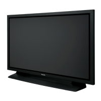
TH-65PF9UK